3.1.1 Bore and Pump Systems
System Overview
Bore System
The bore system provides essential water supply infrastructure and includes production bores, a legacy bore, and various control and safety mechanisms.
Production Bores
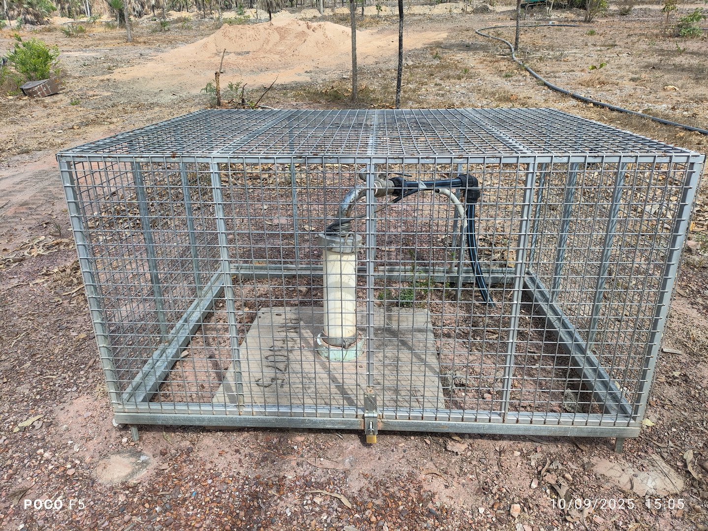
- Bore 1
- Registration number: RN43075
- Location: nearest Bore to the green shed with wire-mesh door, secured in a wire-mesh cage
- Features:
- Isolating valve for head pressure regulation
- Inline pressure gauge
- Power outlet located inside the green shed wire-mesh door, connected to white pump controller panel
- Secured in a mesh box
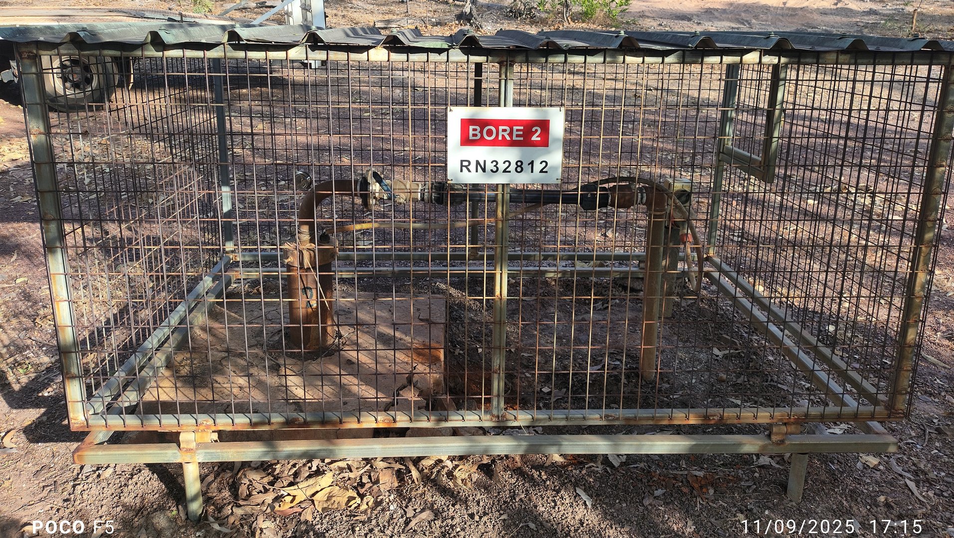
- Bore 2
- Registration number: RN32812
- Location: farest from the green shed with wire-mesh door, secured in a wire-mesh cage with green roof
- Features:
- Isolating valve
- Inline pressure gauge
- Power isolator switch on external pole
- Connected via 3-phase power adapter
- Enclosed in a metal security cage
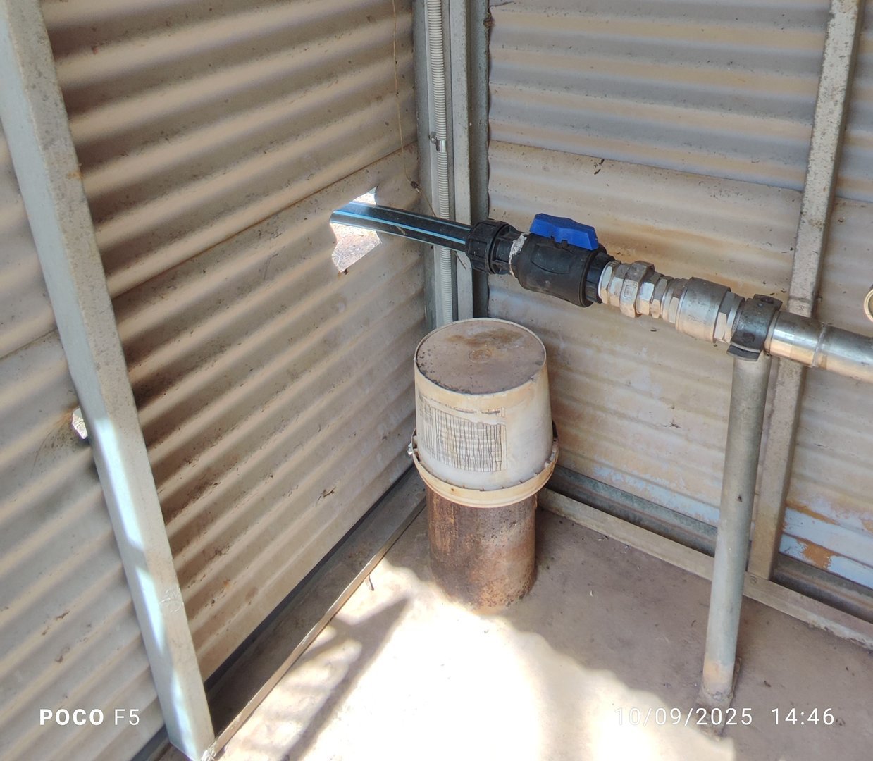
🔹 Legacy Bore
- Registration number: RN31076
- Location: Inside the green shed with wire-mesh doors
- Status: Not in use
- Features:
- Removable cover for pipe
- Retained for reference or backup purposes
Specifications
- System Capacity – 100L per minute
- Water Quality Parameters – See Water Quality
Pump Systems
Overview
The pump system provides automated control and redundancy for continuous operation and includes advanced digital controllers, visual indicators, and fail-safes.
Electrical Supply
- Three-phase power:
- Bore pumps (Bore 1 and Bore 2)
- Single-phase power:
- F60 digital pump controller
- Ultrasonic flow meter
- Chlorine dosing pump
- Main power isolation is located inside the white pump controller panel in the green shed with wire-mesh doors
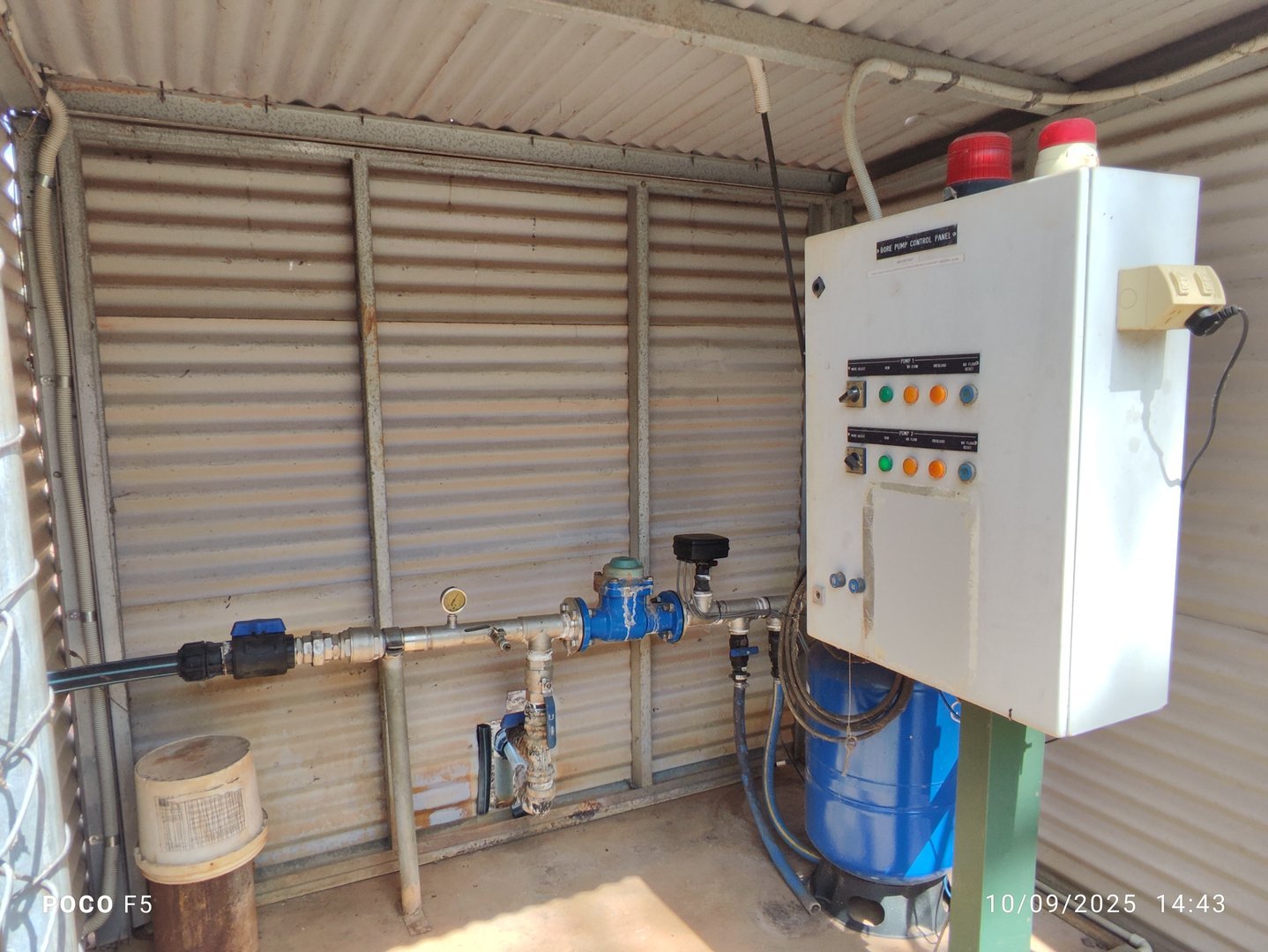
Green Shed with wire-mesh doors (Primary Control Hub)
- Contains:
- F60 digital pump controller
- Bladder pressure tank
- Mechanical flow meter
- Alarm system
- Mode switches and indicators
- Ultrasonic flow meter control box
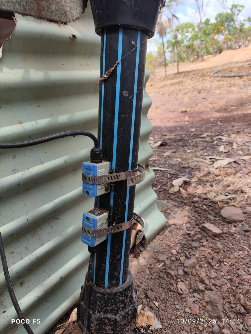
- External pipework contains:
- Ultrasonic flow meter sensors mounted to vertical pipe section
- Flush valve for maintenance and testing
Control Systems
KELCO F60 Digital Pump Controller
- Location: On the pipe manifold in green shed with wire-mesh doors
- Purpose: Regulates pump operation with pressure, flow, and timer control
-
Features:
- Multi-voltage input: 220–240 VAC, 24 VAC/DC, 12 VDC
- Real-time pressure display
- Up to 15 programmable timers
- 40 Amp solid-state switch
- IP64 weatherproof housing
- Suitable for 25 mm (1") pipe and larger
- Remote input for external integration
- Alarm light output and beacon interface
-
Documentation:
.jpg)
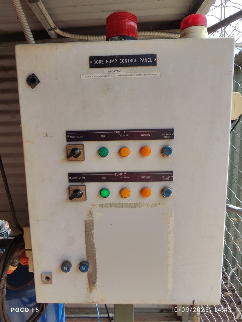
Control Panel Details
- Mode Select Switches:
- Manual, Off, Auto for Bore 1 and Bore 2
- Indicators:
- Green "Run" lights for each Bore (active in manual or auto)
- Red "No Flow" and "Overload" lights (now abandoned)
- "No Flow Reset" button (also abandoned)
- System Status Lights:
- Red "Power On" light on panel top
- Flashing beacon activated by F60 controller on alarm trigger
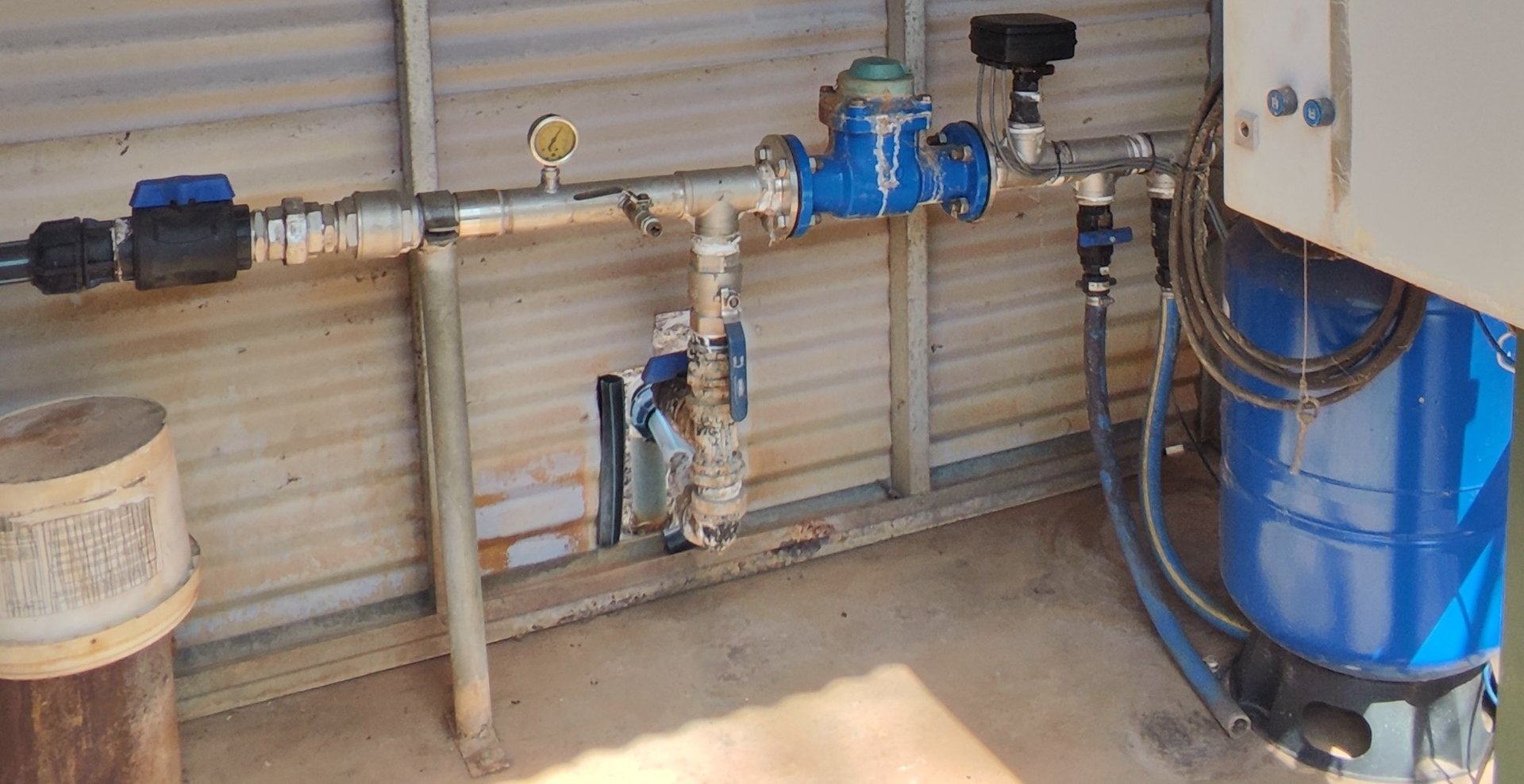
Manifold Area
- Components Located in the Green Shed with wire-mesh doors:
- Mechanical water meter
- Inline pressure gauge
- Pipe manifold joining both Bore lines
- Isolating valves
- Bladder pressure tank (with isolating valve)
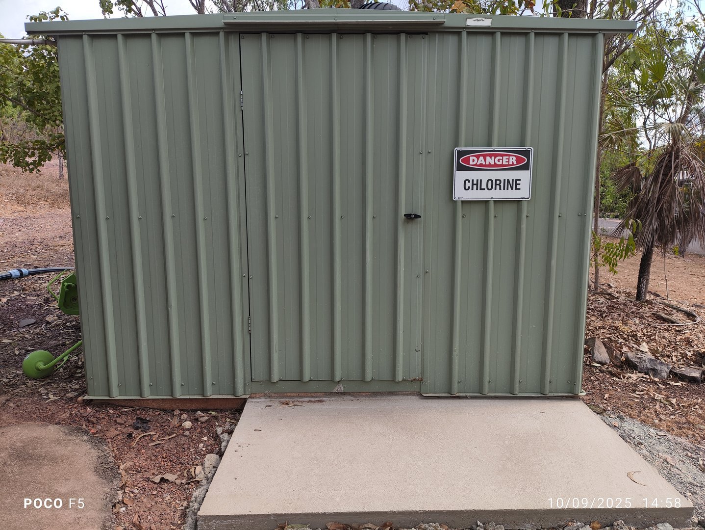
Chlorination System (Second Green Shed)
- Location: Adjacent to green shed with wire-mesh doors
- Contains:
- Chlorine dosing pump
- Dosing tank
- Chlorine chemical storage
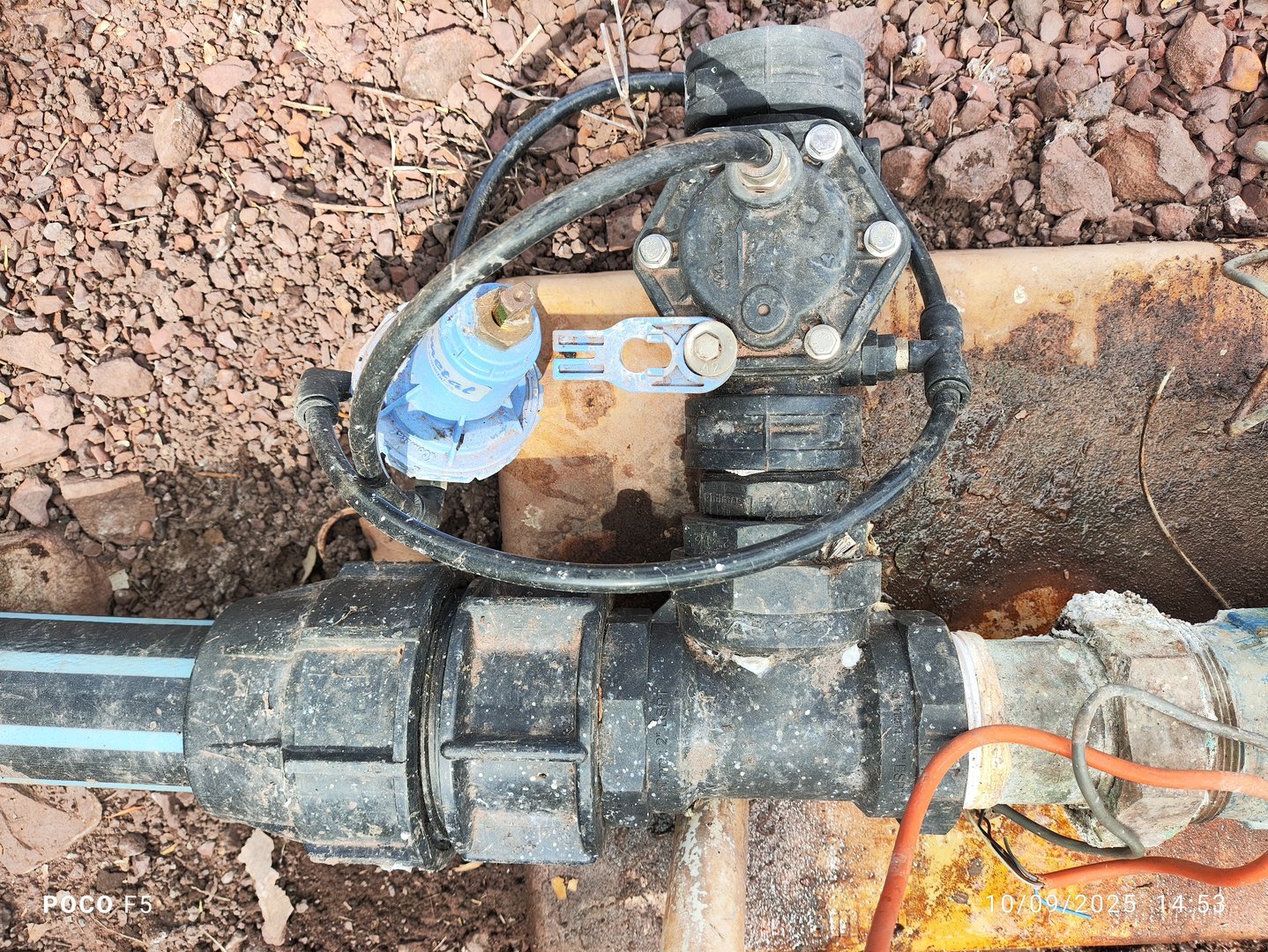
- Injection Point: Installed in Bore line outsite at the easten end of shed
- Monitoring Equipment:
- Secondary mechanical water meter
- Sensor for dosing pump activation
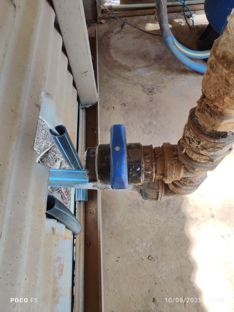
Over-Pressure Emergency Valve
- Purpose: Prevent damage from pump/system failure or closed float valves
- Activation:
- Opens automatically if system remains pressurized beyond safe limit
- Prevents rupture or upstream damage due to over-pressurization
- Location: In-line just before chlorine dosing point
Water Quality
Monitoring
- Frequency: Weekly
- Parameters Tested:
- Turbidity
- Chlorine residual
- Reporting: NT Health Department
- Standards: Aligned with Australian Standards
- References:
See 3.1 Water Supply – Water Quality Parameters
Sampling Procedures
Bore Sampling
- Disinfect tap outlet with 70% alcohol
- Flush for at least 5 minutes until temperature and clarity stabilize
- Collect Samples:
- Microbiological samples first
- Avoid touching bottle rims
- Label immediately with location, date, and sampler ID
Distribution Point Sampling
- Tap Selection: Use cold taps, avoid mixers or filters
- Flush and Disinfect: Remove attachments, flush 5 minutes
- Sample Order: Microbiological → Chemical → Physical
- Sterile Collection: Use lab-approved containers and techniques
Handling and Transport
- Label samples clearly
- Complete sample ID forms and chain-of-custody records
- Deliver to lab within 24 hours
Key Parameters
| Parameter | Target Value / Limit | Importance |
|---|---|---|
| pH | 6.5 – 8.5 | System performance, corrosion control |
| Turbidity | < 4 NTU | Impacts disinfection and filter efficiency |
| Iron | < 0.3 mg/L | Prevents taste and staining issues |
| Manganese | < 0.1 mg/L | Prevents black staining in fixtures |
| Hardness | Monitor only | Impacts scaling in pipes and pumps |
| Microbiological | 0 E. coli/coliforms | Compliance with drinking water safety |
Maintenance
Routine Tasks
- Pump and motor inspections
- Bore flushing and cleaning
- Control panel diagnostics
- Water quality testing and reporting
- Record keeping (logs, service reports)
Version Control
| Version | Date | Description |
|---|---|---|
| 1.0 | 2025-09-10 | Initial Release |
Next Review Date: 2026-03-10