3.1.2 Storage Tanks
This document outlines the specifications and supporting infrastructure for the potable and emergency water storage system at Lake Bennett Estate. The tank farm includes a mix of steel and polyethylene tanks arranged for domestic supply, emergency reserves, and fire-fighting capacity.
System Summary
| Item | Detail |
|---|---|
| Total Storage Capacity | ≈ 449,250 L |
| Tank 1 (Primary Steel Tank) | 309,250 L |
| Tanks 2–5 (Poly, 30 kL) | 120,000 L |
| Tanks 6–7 (Poly, 10 kL) | 20,000 L (emergency reserves) |
| Water Source | Bore feed |
| Tank Locations | Refer to civil drawings (Section 8.1 — to be published) |
| Distribution System | Gravity-fed manifold with isolation valves |
| Outage Behaviour | Gravity distribution continues without power; bore pumps are needed to refill tanks (~3½–4 days dry season / ~30 days wet season without refill). See 3.3.2 Backup Power |
| Monitoring | Mechanical and ultrasonic flow meters |
| Control Points | Float valves, manual isolation taps, flush and air release valves |
Tank 1 — Rhino RT-310 Steel Storage Tank
| Item | Detail |
|---|---|
| Quantity | 1 |
| Manufacturer | Rhino Tuff Tanks (Kingspan Rhino Tanks) |
| Model | RT-310 |
| Total Capacity | 309,253 L (usable: ~309,250 L) |
| Dimensions | Ø 11.65 m × H 2.9 m |
| Construction | Corrugated galvanised steel with polyethylene liner (Infinity Poly X) |
| Certifications | AS/NZS 4020 – Potable Water; AS/NZS 1170 – Structural; AS/NZS 4600 – Steel Structures |
| Warranty | 20-year pro-rata (tank and liner) |
| Ancillary Equipment | Bore-fed inlet (poly pipe) with isolation tap; internal float valve; mechanical level indicator; overflow safeguard pipe; manhole access; isolation valves at base |
| Primary Use | Potable water supply and fire-fighting storage |
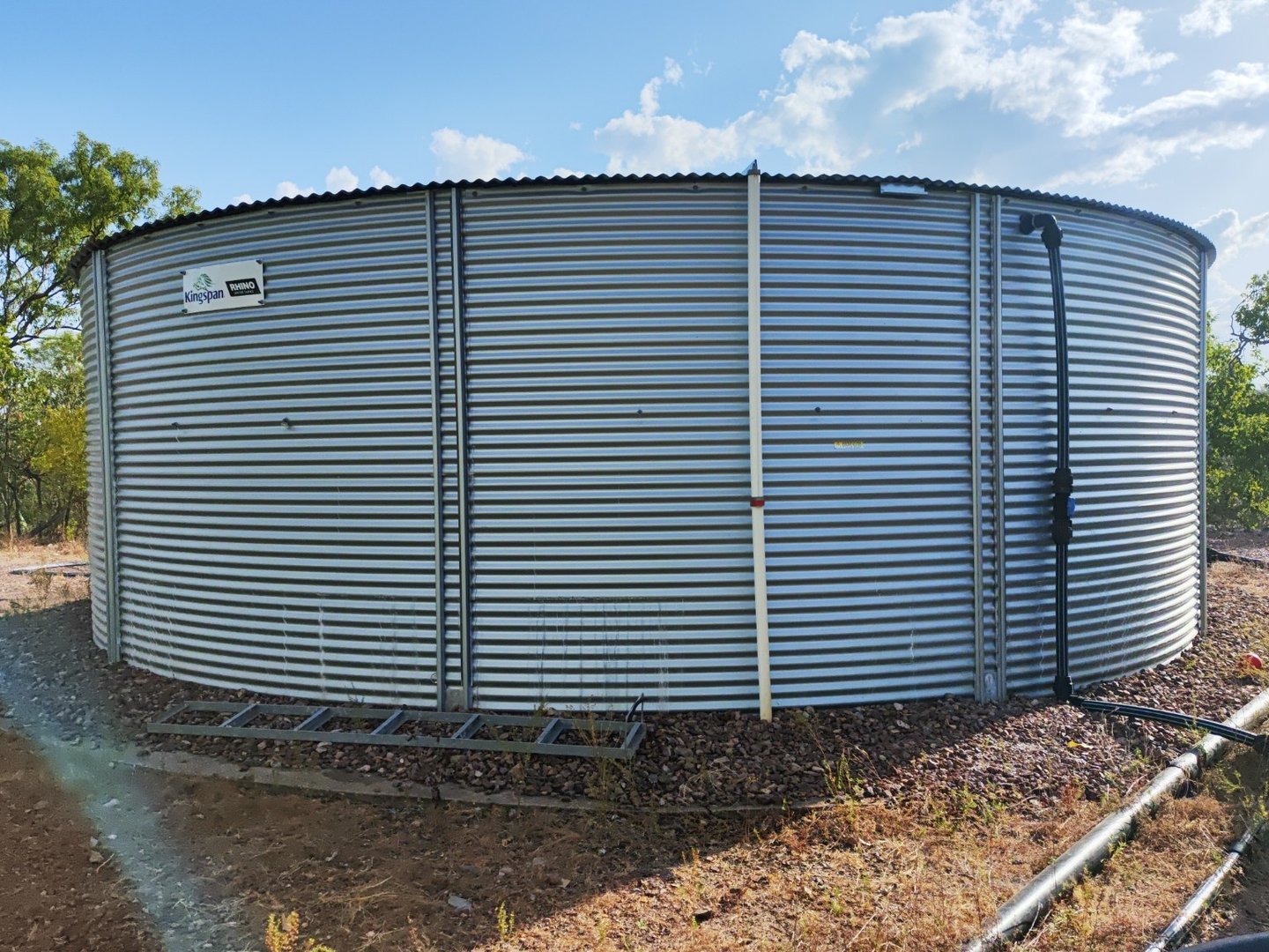
Manufacturer Resources:
Tanks 2–5 — Terracorp 30,000 L Poly Tanks
| Item | Detail |
|---|---|
| Quantity | 4 |
| Model (Approx) | WT30 |
| Individual Capacity | ~30,000 L |
| Total Group Capacity | ~120,000 L |
| Dimensions (each) | Ø 3450 mm × H 3390 mm |
| Construction | UV-stabilised, food-grade polyethylene (ribbed) |
| Warranty | Typically 10 years |
| Ancillary Equipment | Bore-fed inlets with isolation taps; internal float valves; top-mounted level indicators; overflow drains; manhole access; base manifold with individual tank isolation |
| Primary Use | Potable water buffer/storage |
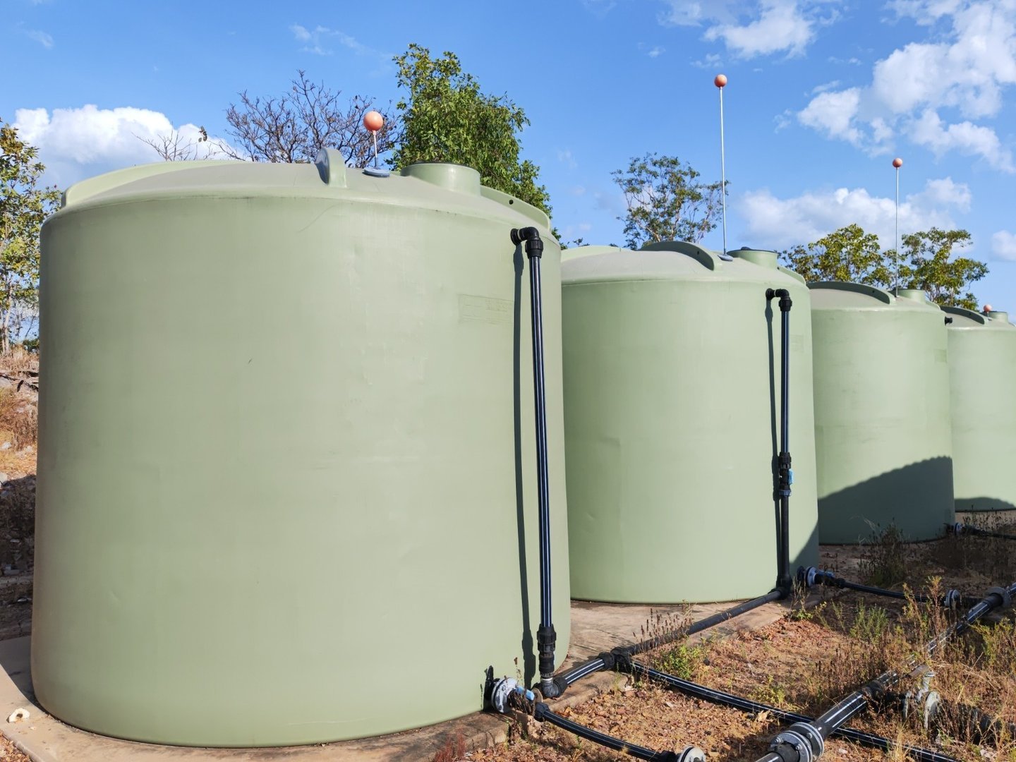
Manufacturer Resources:
Tanks 6 & 7 — Terracorp 10,000 L Poly Tanks
| Item | Detail |
|---|---|
| Quantity | 2 |
| Model (Approx) | WT10 |
| Individual Capacity | ~10,000 L |
| Total Group Capacity | ~20,000 L |
| Dimensions (each) | Ø 2400 mm × H 2220 mm |
| Construction | UV-stabilised, food-grade polyethylene (ribbed) |
| Warranty | Typically 10 years |
| Ancillary Equipment | Bore-fed via shared line; linked by small manifold; overflows and manhole access; no float valves installed |
| Primary Use | Emergency and fire reserve |
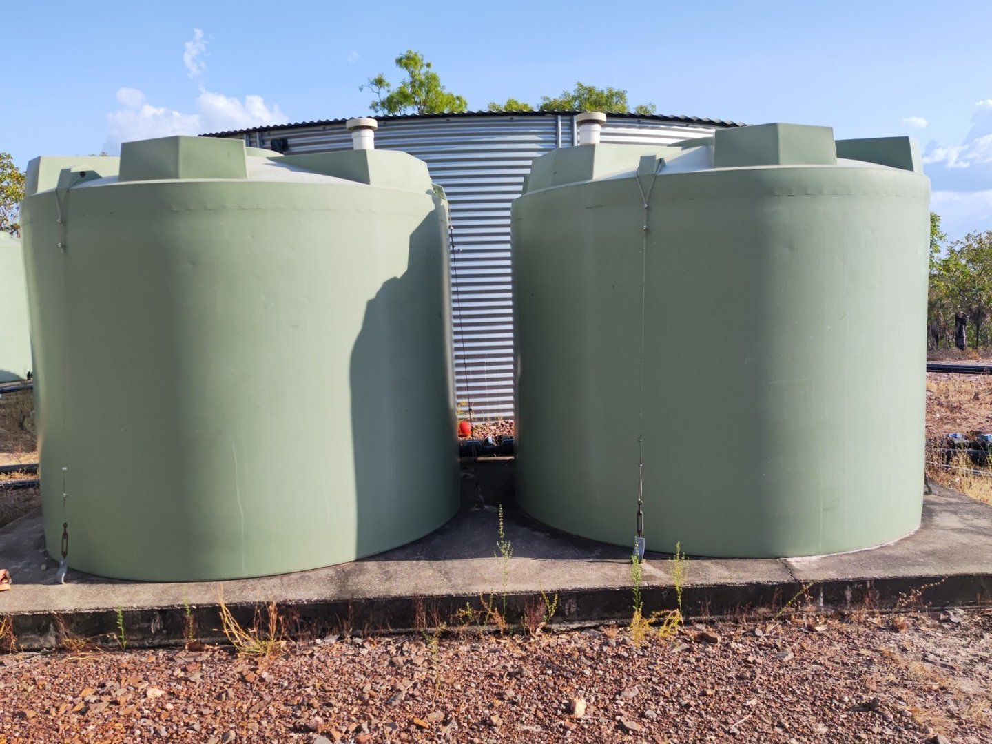
Manufacturer Resources:
Piping and Control Infrastructure
Manifolds and Isolation
- Tanks 2–5 connected at the base via a shared poly manifold
- Each tank has a blue-handle isolation tap
- Master tap installed at the end of the line
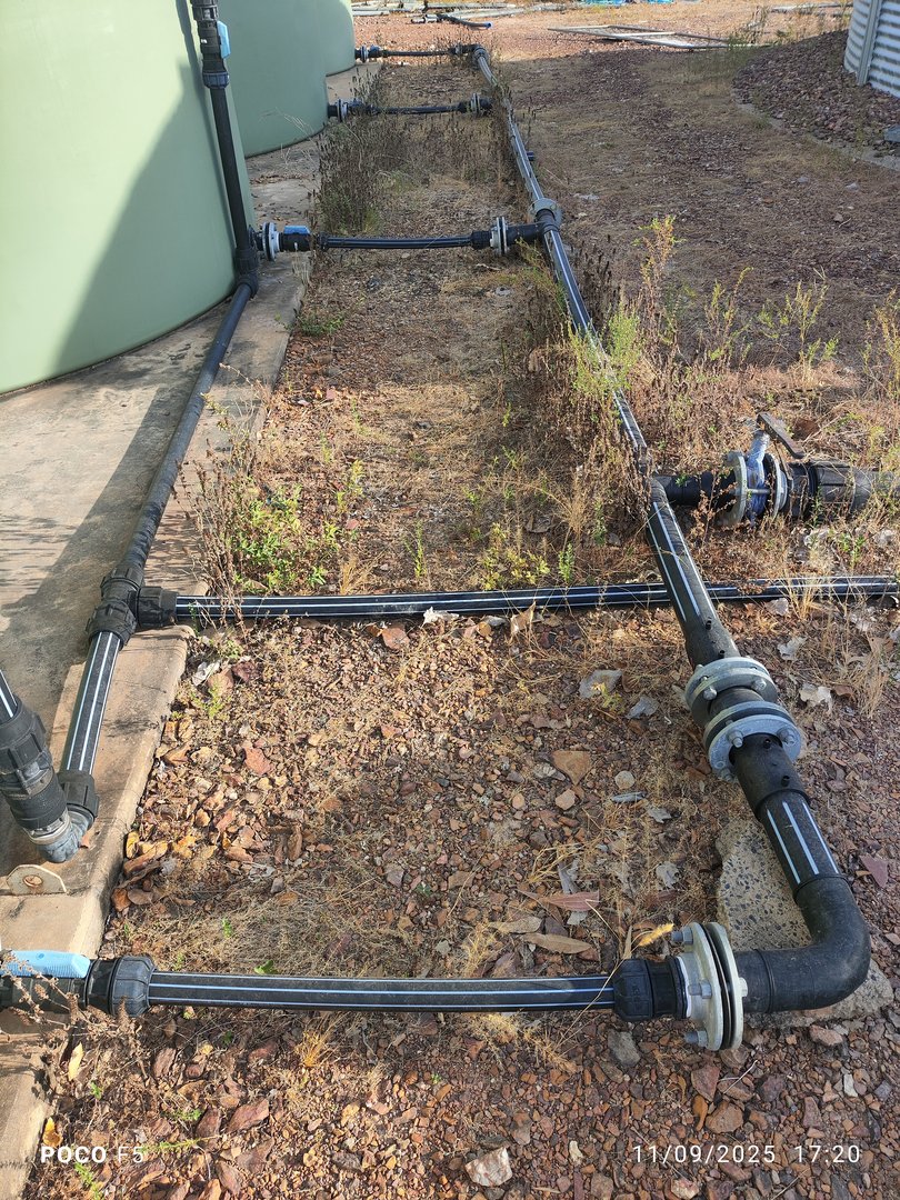
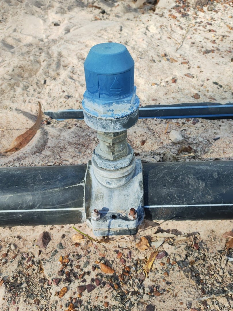
Air Valve
- Installed on main gravity-fed line
- Equalises air pressure during tank isolation or line filling
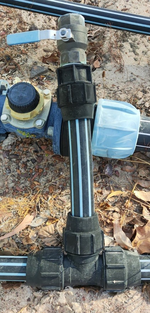
Bore Inlet Isolation and Flush Valve
- Flush Valve: Installed on bore line, used biannually to clean the main supply line
- Isolation Valve: Full-bore manual tap to shut off bore feed during maintenance

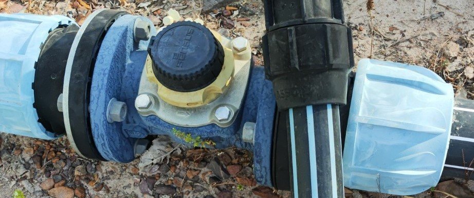
Monitoring Systems
Mechanical Water Meter
- Located on main output line
- Tracks cumulative flow from all tanks
Ultrasonic Flow Meter
- Digital display unit for live flow rate monitoring
- Installed in line after mechanical meter

Safety Systems
- Overflow Pipes: Installed on all tanks to prevent structural overfilling
- Float Valves: Tanks 1–3 include bore shutoff floats
- Removable Ladder: Used for access to Tank 1, stored off-system when not in use
Version Control
| Version | Date | Description |
|---|---|---|
| 1.0 | 2025-09-10 | Initial Release |
Next Review Date: 2026-03-10