3.2.1 SSP1 Main Septic
This section details the Main Septic Tank and Lift Well serving Bungalows 17–59, designated as SPS1 (SSP1) in the collection network Zone 1.
Location and Overview
- Location: Adjacent to the causeway, near the access road to Bungalows 17–59
Role in Collection Network
SPS1 (SSP1) serves Zone 1 of the collection network. It receives gravity sewer from Bungalows 17–59 and Zone 3 effluent that arrives via the SPS3/SSP3 under-lake rising main at the Unit 40 access pit (MH A), then the Zone 1 gravity main. Primary treated effluent is routed to WWTP Primary Tank 1 (PT-1).
Primary Septic Tank
Tank Specifications
| Item | Detail |
|---|---|
| Type | Precast concrete |
| Capacity | ~18,000 L |
| Dimensions | Approx. 2.4 m diameter, 6.0 m length |

Access Lids (Hook Lifter)
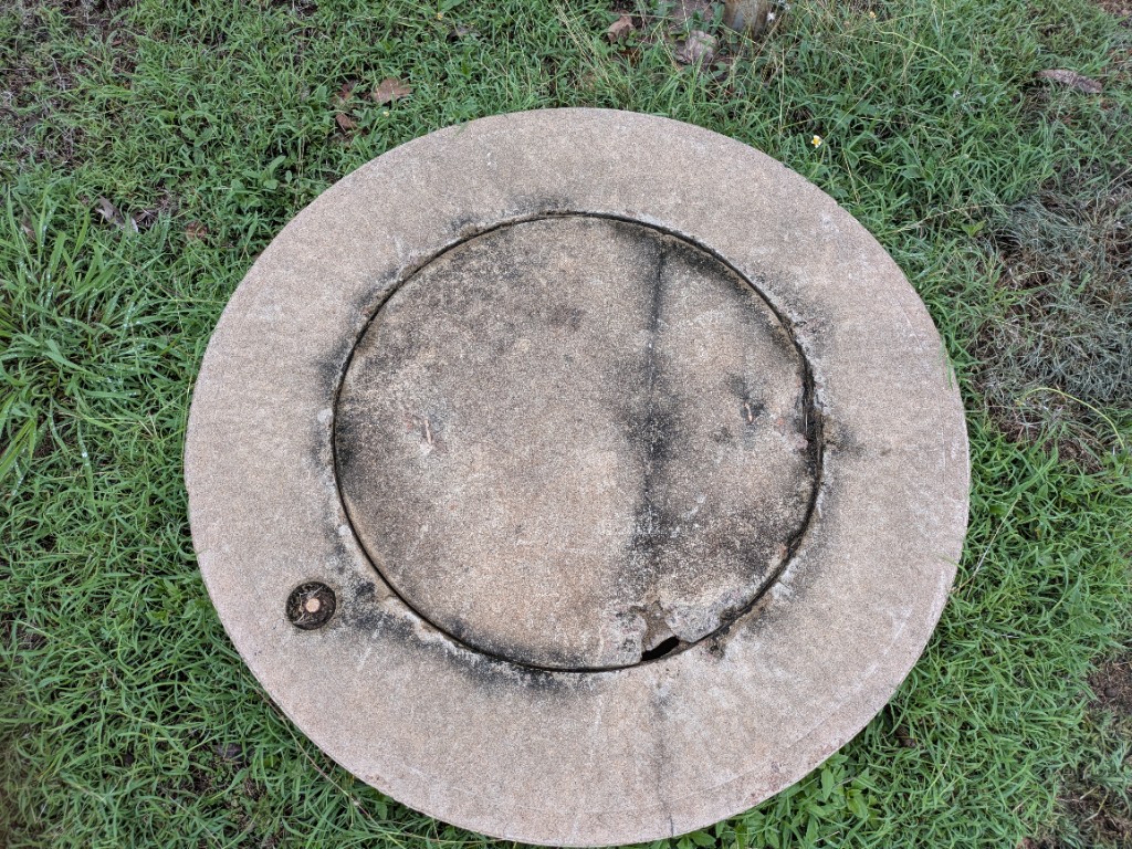
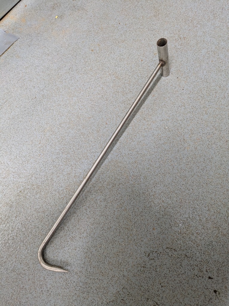
The ~18,000 L primary septic has concrete access lids in outer rings. Open them with a hook lifter only.
| Item | Detail |
|---|---|
| Lid type | Circular concrete lid in concrete ring |
| Open with | Hook lifter |
| Do not use | Crowbar, pry bar, or similar — they damage the concrete lids (chips and broken edges) |
| Also used for | Tank lids at SSP5 / Pit 5 |
| Stored | WWTP control room — collect before use; return after |
Open With a Hook Lifter
Use a hook lifter on the 18,000 L tank lids. Do not use a crowbar — it chips and breaks the concrete. The estate hook lifter is kept in the wastewater plant control room (same tool for Pit 1 and Pit 5 tank lids).
Flow System
- Inflow: Gravity sewer from Bungalows 17–59 (DN150 common main), including Zone 3 effluent that enters at the Unit 40 access pit (MH A) from the SSP3 under-lake rising main
- Discharge: Primary treated effluent to WWTP Primary Tank 1 (PT-1)
Site After 2026 Tank Removals
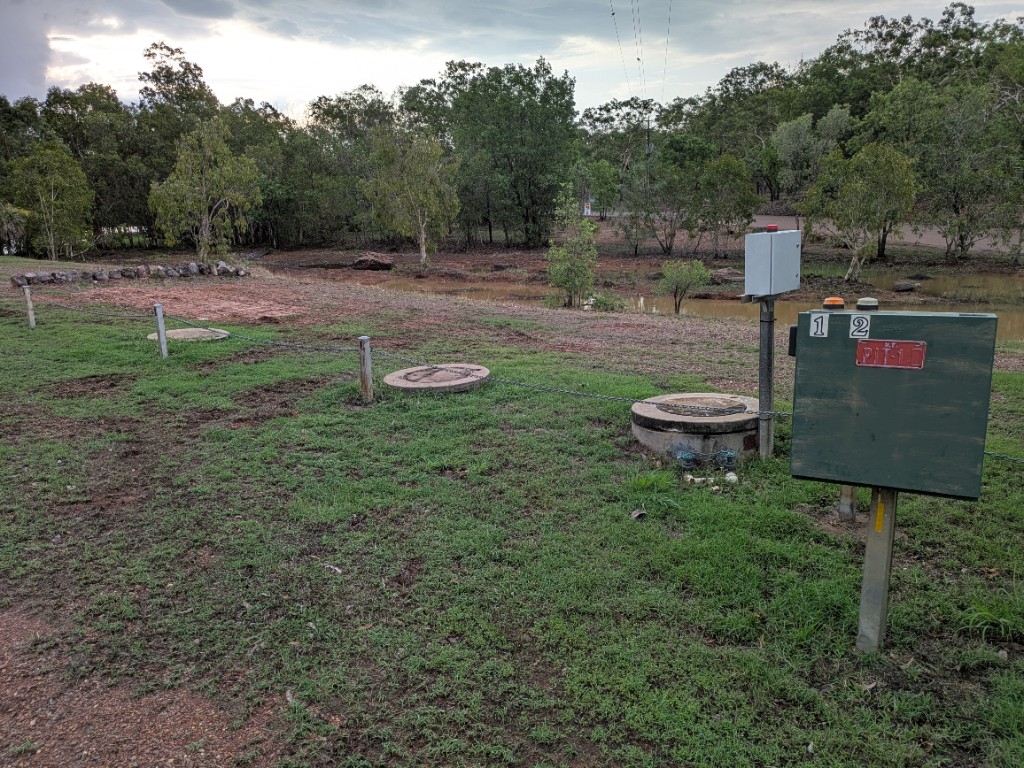
On 26 October 2026, two 5,000 L tanks at Pit 1 / SSP1 were removed and the ground reinstated. Remaining plant at the station is the ~18,000 L primary septic, the lift well, the green power switch box (N.T. PIT-1 plate), and the white Pit 1 control panel enclosure (see site photo under Location and Overview). Closed-out record: 5.2 Installations, Upgrades, and Repairs.
Electrical Enclosures at Pit 1 (Two Boxes)
There are two separate enclosures beside the lift well. Do not confuse them: the green box with the N.T. PIT-1 plate is power / circuit breakers, not the pump controller.
| Enclosure | Appearance | What it is | Contents / indicators |
|---|---|---|---|
| Power switch box | Larger green metal box; red N.T. PIT-1 plate; white 1 and 2 labels | Power switchboard for Pit 1 and Pit 2 | Circuit breakers for Pit 1 and Pit 2; 15 A general-purpose power point on its own circuit breaker; orange indicator lights on top — show that power is available to Pit 1 and Pit 2 |
| Pit 1 control panel | Smaller white / light grey enclosure; red light on top | Pump control for Pit 1 only | HydroStart dual-pump controller (and related controls); the red light on top is the alarm indicator |
Green Box Is Power, Not Control
The green enclosure labelled N.T. PIT-1 is a power switch box. It feeds Pit 1 and Pit 2 and holds their circuit breakers. The white box is the Pit 1 control panel; its red top light is the alarm.
Lift Well System
Lift Well Structure
- Type: Precast concrete (appears to be 2.4 m diameter pipes)


Discharge Manifold (Green Isolation Taps)
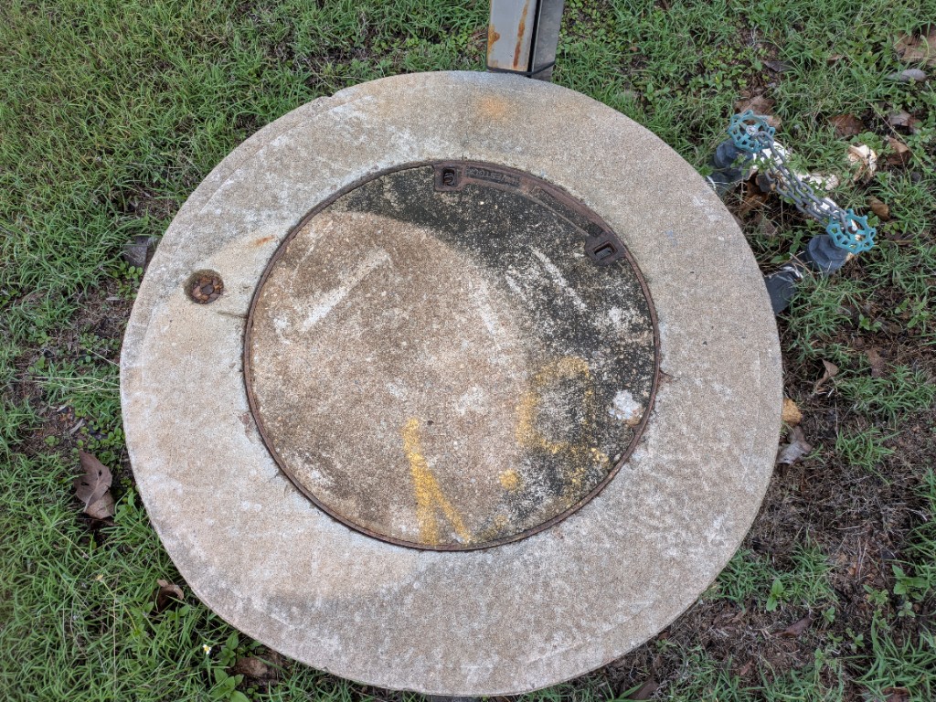
Beside the lift well, the pump discharge manifold has two green taps (ball valves). Each tap isolates one pump and that pump’s non-return valve (NRV).
| Item | Detail |
|---|---|
| Quantity | Two green isolation taps (one per pump) |
| Isolates | That pump’s discharge leg and its non-return valve |
| Use case | NRVs can block from time to time — close the matching green tap to isolate that pump/NRV so the valve can be cleaned or replaced without taking the whole station offline |
Isolate One Pump at a Time
Close only the green tap for the pump/NRV being worked on. Leave the other pump’s tap open so duty/standby can continue if the controller allows.
Access Lid (Gatic)
The lift-well lid is a concrete cover in a metal frame with recessed Gatic lifting slots. It replaced the earlier metal-handle style lid (works associated with the October 2026 Pit 1 programme — see 5.2).
| Item | Detail |
|---|---|
| Lid type | Concrete access cover in metal frame (no protruding handle) |
| Open with | Gatic lifter only — insert into the recessed slots |
| Do not use | Crowbar, pry bar, or similar — they can chip or crack the concrete lid |
| Tool on site | Plumboss Gatic lifter |
| Stored | WWTP control room — collect before opening the Pit 1 lift-well lid; return after use |
Open With a Gatic Lifter
Use a Gatic lifter in the recessed slots. Do not lever this lid with a crowbar — it damages the concrete. The estate lifter is kept in the wastewater plant control room.
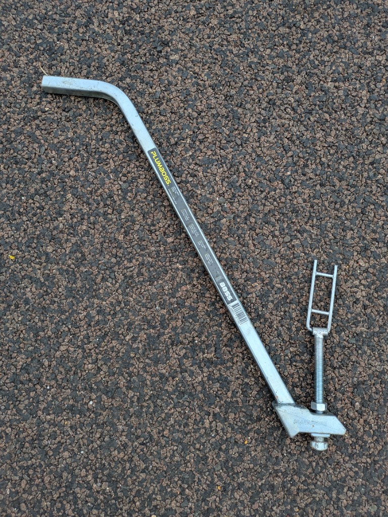
Pump System
| Item | Detail |
|---|---|
| Configuration | Duty and standby pump set |
| Type | Xylem 3069 Series Submersible Pump |
| Manufacturer | Xylem Water Solutions |
| Power | 3.6 kW / 2.5 hp |
| Flow Rate | Max 2640 L/min |
| Max Temperature | 40°C |
| Power Supply | Three-phase |
| Serial Numbers | 3069 1720 1139 254 / 3069 1720 2446154 |
| Installation | 2 units |
| Manual | Xylem 3069 Series Operating Manual |
Control System
The Pit 1 HydroStart controller is inside the smaller white enclosure (not the green N.T. PIT-1 power switch box). See Electrical Enclosures at Pit 1.
Controller
| Item | Detail |
|---|---|
| Enclosure | White / light grey meter box beside the green power switch box |
| Type | HydroStart Dual Pump Controller |
| Manufacturer | MATelec Australia |
| System Status Indicators | Power On, Enabled, Level Alarm |
| Pump Status (both pumps) | Auto/Manual, Pump On, Fault |
| Manual | HydroStart Standard Manual |
Float Switches
| Item | Detail |
|---|---|
| Quantity | 2 units (pump activation and high level) |
| Model | Kelco K10M |
| Voltage | 0–240 V, 15 A resistive |
| Type | SPDT Float Switch |
| Cable | 10 m CPE rubber |
| Manufacturer | Kelco (Australia) |
| Documentation | K-Series Installation Sheet |
Wiring Note
Blue wire is common.
Alarm System
- Features: Visual and audible alarms on the Pit 1 control panel
- Red light (top of white enclosure): Alarm indicator for Pit 1
- Do not confuse with: Orange lights on the green power switch box — those show power available to Pit 1 and Pit 2, not an alarm
Version Control
| Version | Date | Description |
|---|---|---|
| 1.0 | 2025-10-06 | Initial Release |
| 2.0 | 2026-06-22 | Updated flow paths for WWTP upgrade |
| 2.1 | 2026-10-21 | Added Show on Map locate buttons |
| 2.2 | 2026-10-26 | Two 5,000 L tanks removed; post-works photo of Pit 1 |
| 2.3 | 2026-10-26 | Lift-well Gatic lid — open with Gatic lifter only; do not crowbar |
| 2.4 | 2026-10-26 | Plumboss Gatic lifter photo; stored in WWTP control room |
| 2.5 | 2026-10-26 | 18,000 L tank lids — hook lifter only; do not crowbar |
| 2.6 | 2026-10-26 | Hook lifter photo; WWTP control room; also for Pit 5 lids |
| 2.7 | 2026-10-26 | Clarified green N.T. PIT-1 power switch box vs white Pit 1 control panel |
| 2.8 | 2026-10-26 | Moved Unit 17 gravity-main access-chamber photo to 3.2.6 |
| 2.9 | 2026-10-26 | Current site photo (post tank removal) as main location image |
| 2.10 | 2026-10-30 | Hidden search aliases (pit 1 / SPS1 / SSP1) |
| 2.11 | 2026-10-30 | Zone 3 inflow via Unit 40 access pit (MH A), then Zone 1 gravity main |
| 2.12 | 2026-11-01 | Discharge manifold — two green taps isolate each pump and NRV for clean/replace |
Next Review Date: 2027-04-26