3.3.1 Grid
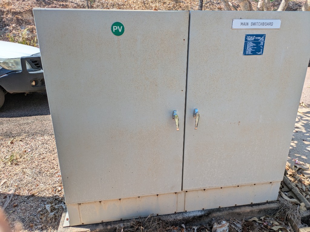
Main Switchboard (Units 37–38)
- Location: Between units 37 and 38, east side; fed from an overhead power line
| Item | Detail |
|---|---|
| Meters | Units 30 through 34 |
| Streetlights | Legacy meters for lights between units 43–44 and 29–30 |
| Supply | Primary grid connection to the estate |
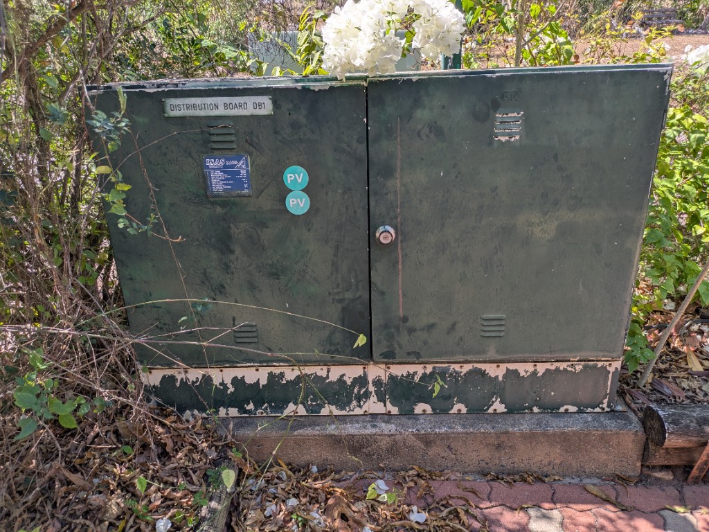
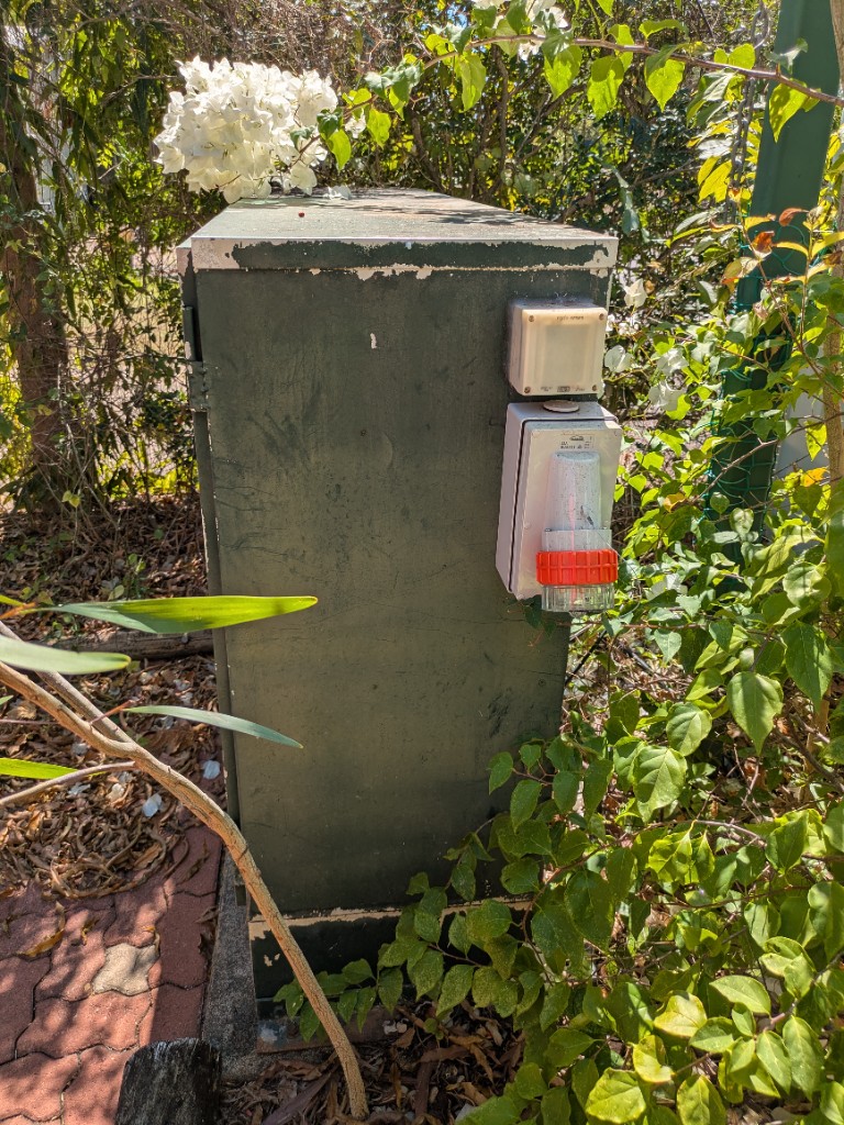
Distribution Board DB1 (Near Unit 22)
- Location: Near unit 22 on the east side
| Item | Detail |
|---|---|
| Meters | Units 17–29; three meters for the bores and sewerage pits (Pit 1 and Pit 2) |
| Streetlights | Functioning streetlight between units 19 and 20 |
| Generator Inlet | Hire ~30 kVA three-phase generator for storm standby or prolonged outages |
Potable supply is gravity-fed from hill tanks (days to weeks without bore refill, season-dependent); Pit 1 and Pit 2 pumps typically require generator power within ~12 hours. See 3.3.2 Backup Power.
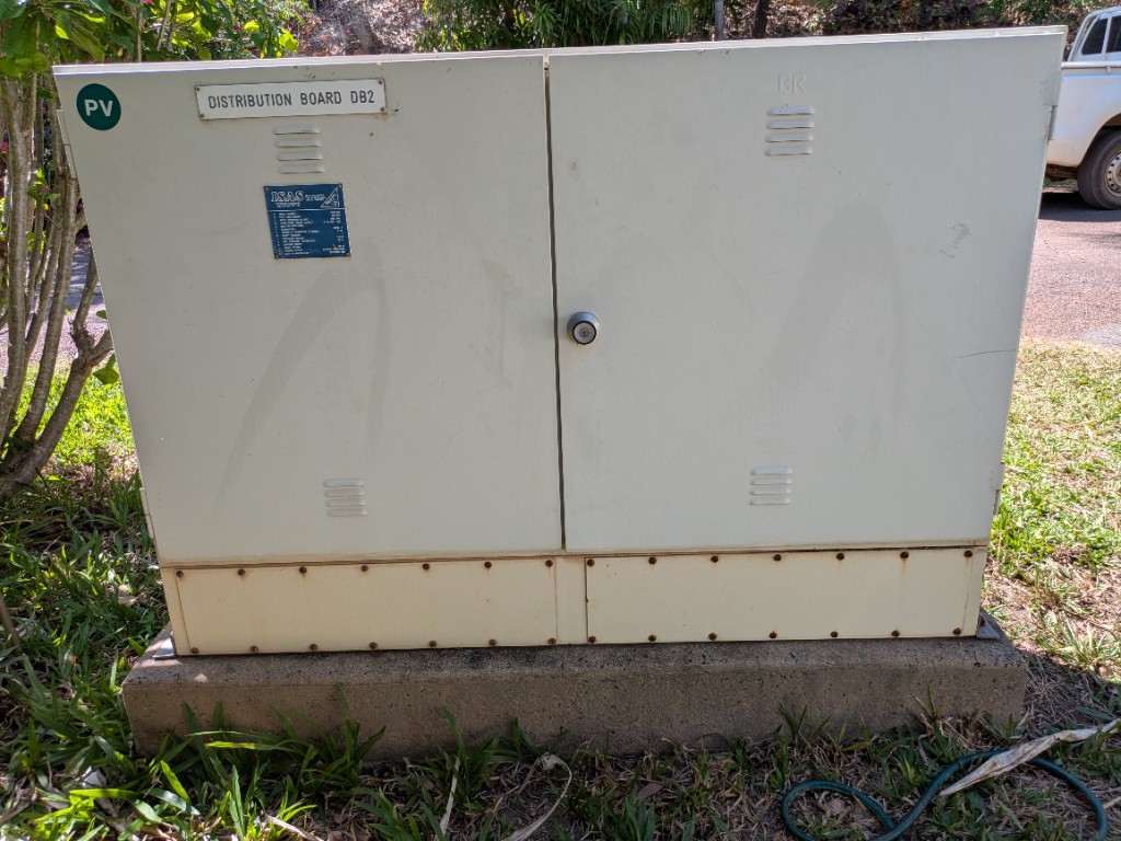
Distribution Board DB2 (Near Unit 51)
- Location: Near unit 51
| Item | Detail |
|---|---|
| Meters | Units 45–58 |
| Streetlights | Units 56–58 and 55–56 (not functioning) |
West Side Main Switchboard (DSB-DB1)
- Location: Between units 66 and 75
| Item | Detail |
|---|---|
| Function | Connects the west side to the public network |
| Meters | Units 66–75 |
| Streetlights | Non-functioning streetlight in that area |
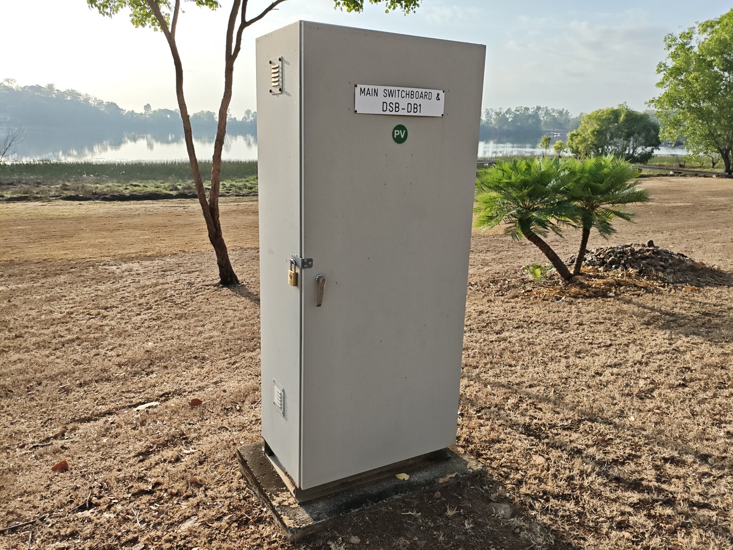
Sewerage Pit 3 Distribution Box
- Location: Near Pit 3
| Item | Detail |
|---|---|
| Meters | Pit 3 and Pit 4 (on the same meter) |
| Streetlights | Non-functioning streetlight between units 65 and 66 |
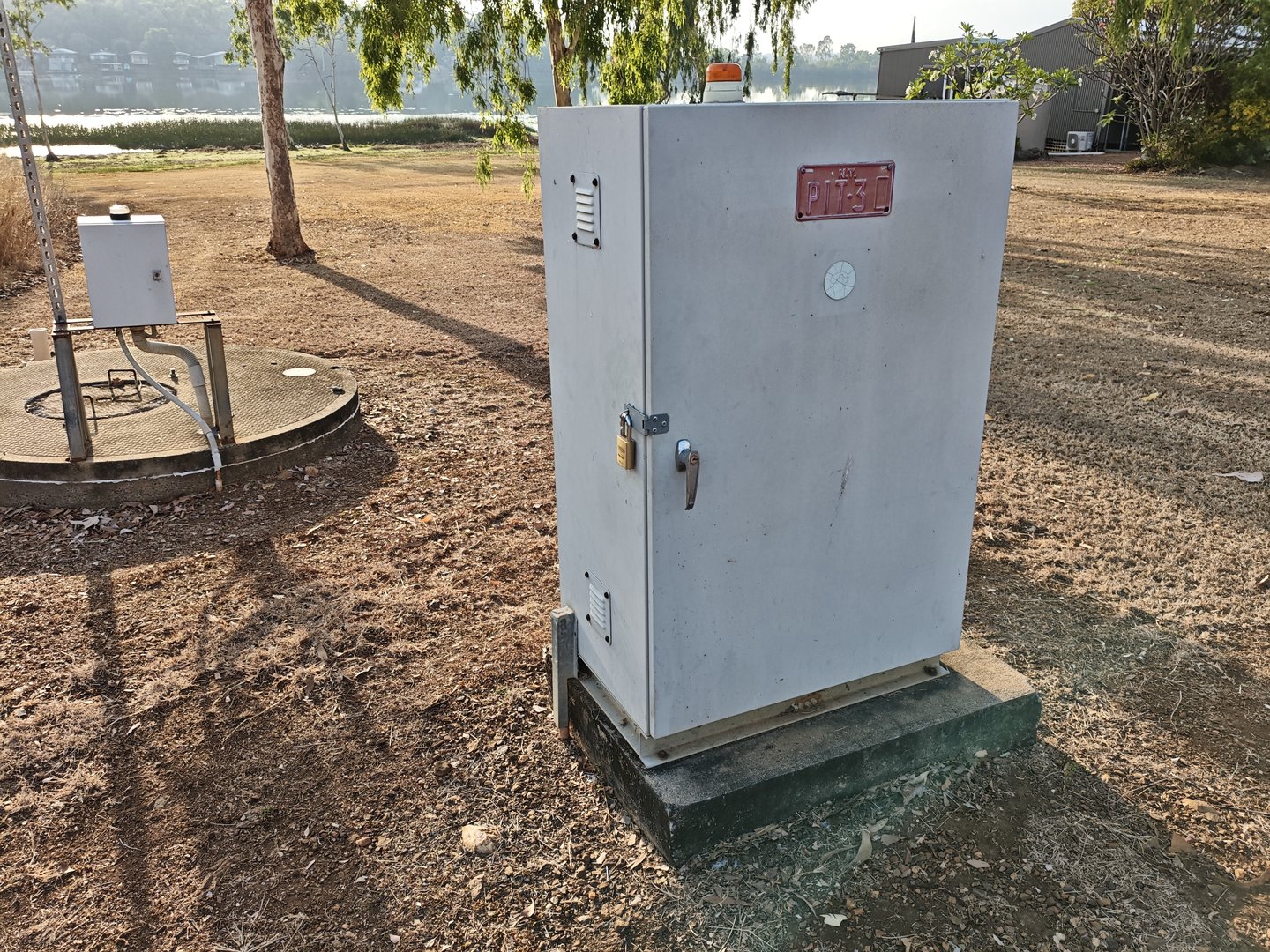
Pit 5 Distribution Box
- Location: Near Pit 5
| Item | Detail |
|---|---|
| Controls | Pit 5 |
| Meters | Units 75, 76, 79, and 80 |
| Streetlights | Units 75–80 (not functioning) |
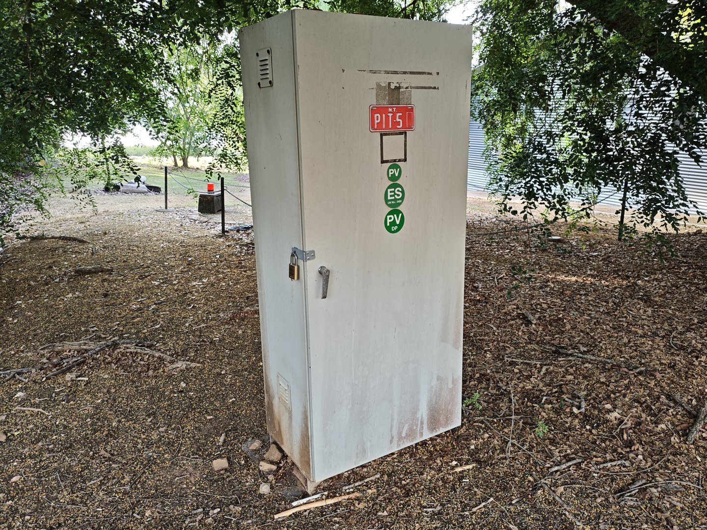
North Shore Main Switchboard (Near Unit 7)
- Location: North shore near unit 7
| Item | Detail |
|---|---|
| Function | Grid connection for the north shore |
| Meters | Units 1–16 |
| Streetlights | Legacy streetlights that no longer function |
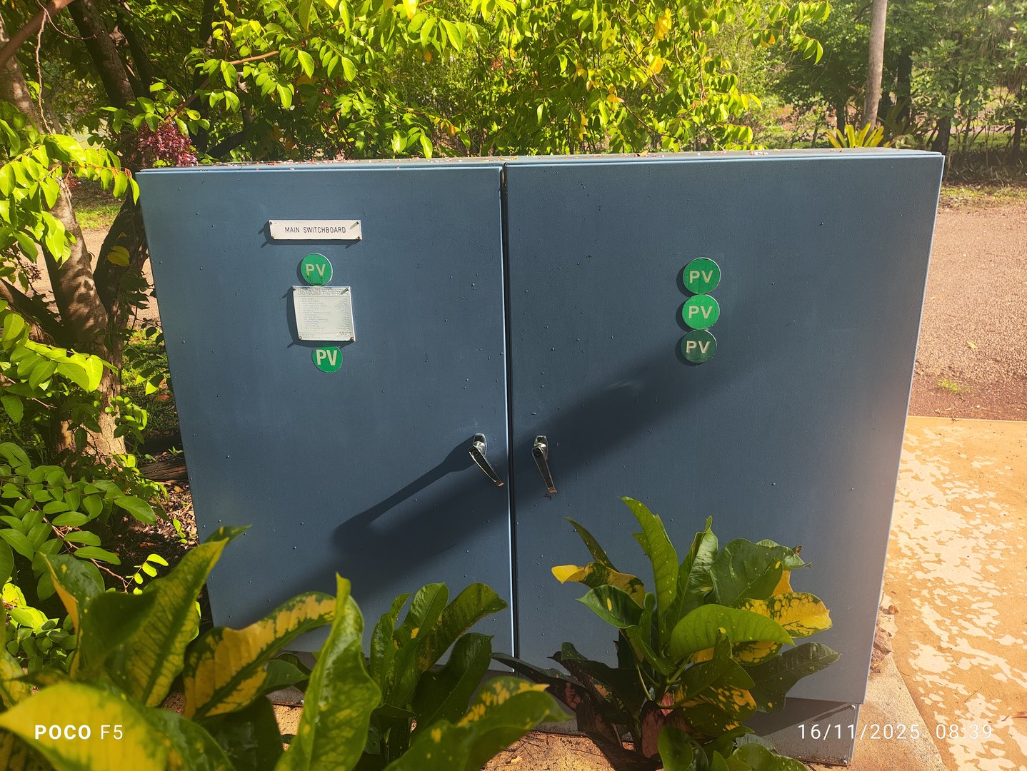
WWTP Control Room
The treatment plant has its own wall-mounted distribution board (WWTP DB) inside the control room: 63 A main, then Control Panel, Aircon, Power, and Lights circuits. An in-ground electrical pit sits behind the container. See 3.2.13 Power Distribution Board and Electrical Pit.
Version Control
| Version | Date | Description |
|---|---|---|
| 1.0 | 2025-10-06 | Initial Release |
| 1.1 | 2026-08-29 | Added switchboard photos; DB1 generator inlet documented |
| 1.2 | 2026-08-30 | Linked WWTP control-room distribution board |
| 1.3 | 2026-08-30 | Linked electrical pit behind the WWTP control room |
Next Review Date: 2026-04-06