3.2.16 T-COM Control Interface
Orenco T-COM is the telemetry control system for the Lake Bennett AdvanTex® wastewater treatment plant. The same controller and point database are reached three ways:
| Interface | Page | Typical use |
|---|---|---|
| Web browser | 3.2.17 T-COM Web Interface | Phone / tablet / PC on the plant network |
| T-COM Viewer (text console) | 3.2.18 T-COM Viewer | ENVR remote monitoring — telnet-style System Status Display |
| Local LCD touchscreen | 3.2.19 T-COM Local HMI | Onsite in the WWTP control room |
Based on the LBC OWMS O&M Manual V1.1 (Appendices 12–14), Orenco EIN-CP-SET-5898, EIN-TCOM-SW-2, and drawing set EDW-CD-TCOM-5535.
Authorised Personnel Only
Only trained personnel may operate the WWTP via T-COM (web, Viewer, or local HMI). If in doubt, contact ENVR on 0402 524 033 or Tim Earl on 0417 892 281.
Do Not Change Settings Without Authority
Changing timer ratios, pump enables, or alarm setpoints without Orenco / ENVR authorisation can void warranty cover and upset treatment performance. Default practice: view and report.
This is not the estate 3.4 Flow Monitoring web panel.
How the Three Interfaces Fit Together
| You are… | Reach for… | Because… |
|---|---|---|
| In the control room after a walkover or alarm | Local HMI (+ HOA column) | Fastest visual status on site |
| Offsite with a phone / laptop on the plant network | Web interface | Same points, browser UI, screenshots in this manual |
| ENVR doing weekly monitoring or monthly log export | T-COM Viewer | Text console, Expanded Reports, Program Mode |
All three write the same controller. Changing a value in one place changes it everywhere — including constraints that can lock the HMI out of a point until status returns to Automatic.
What T-COM Is
| Item | Detail |
|---|---|
| Role | Monitor and control floats, valves, sensors, pumps, UV, AX fan, and alkalinity feed |
| Manufacturer | Orenco Systems® Inc. / Orenco Controls |
| Panel model | TCOM-DAX/DDAX/S/DAX380 3Ø TSD XF LCFA (2)UV (2)CV fm (AUS/NZ) |
| Drawing set | EDW-CD-TCOM-5535 (approved 10 Jun 2025) |
| Controller | ATRTU-TCOM board (TCOM1 on the backplate) |
| Location | WWTP control room — 3.2.13 Control Room |
| Power | CONTROL PANEL breaker on WWTP DB — 3.2.13 Power Distribution Board |
| Network | Ethernet switch ETH_SW1 · MikroTik WiFi in control room · optional 4G telemetry |
Plant process: 3.2.10 WWTP Overview.
Credentials Not Published
Usernames, passwords, IP addresses, ports, and cellular details are not published here. ENVR holds live credentials.
Panel Hardware (Shared)
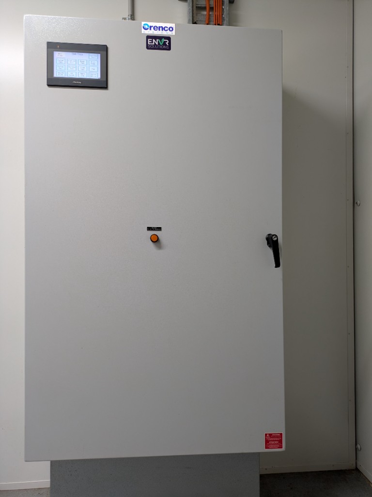
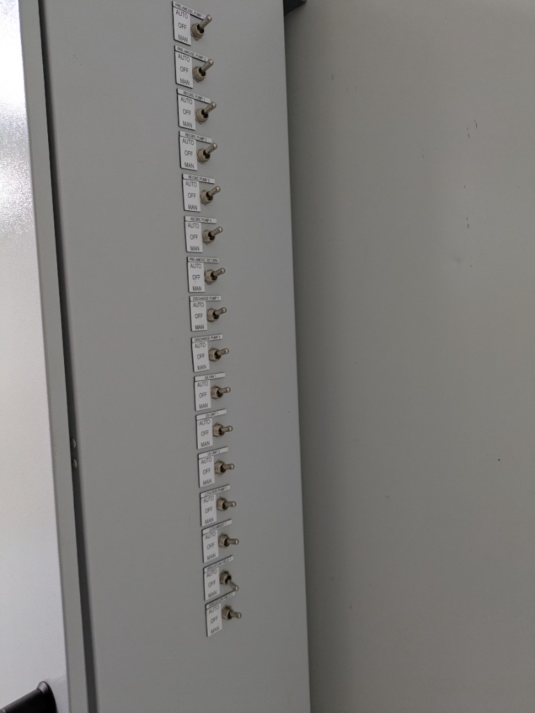
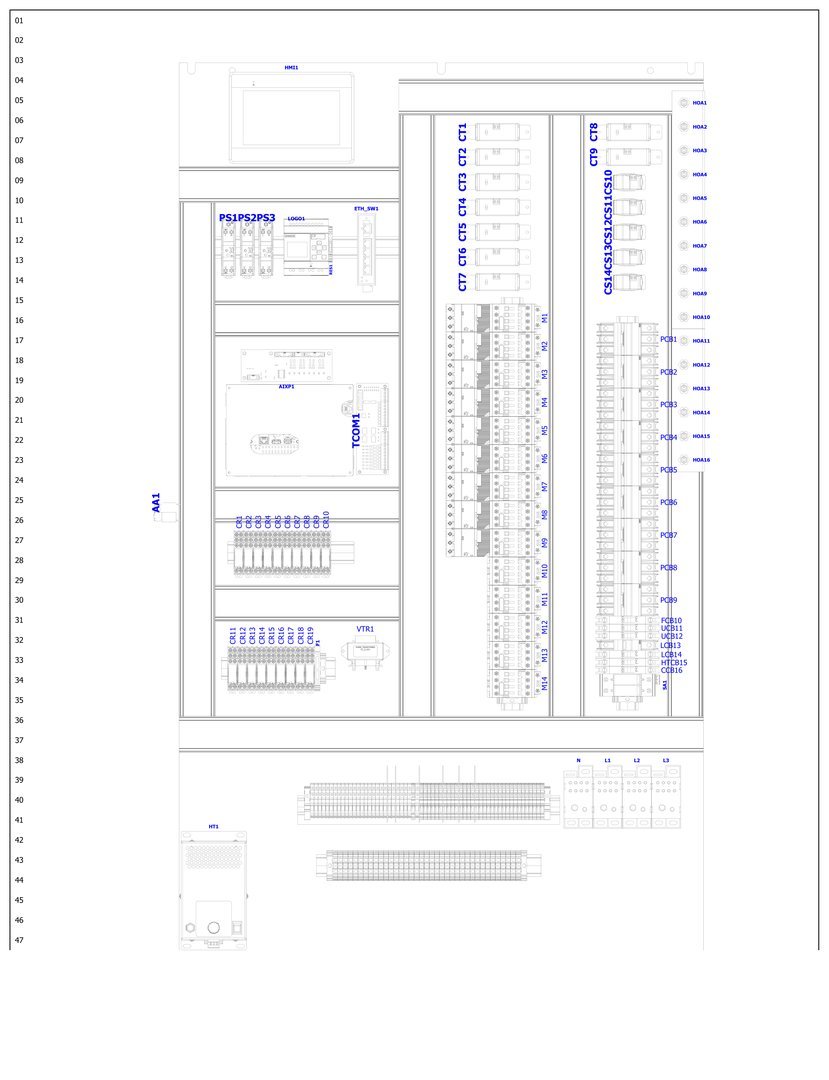
The three software interfaces all drive the same panel. Door (LCD HMI1) and backplate layout (Appendix 13, Sheet 15):
| Tag | What it is | Operator relevance |
|---|---|---|
| HMI1 | Colour LCD touchscreen | 3.2.19 Local HMI |
| TCOM1 | ATRTU-TCOM board | Logic, logs, web server, remote access |
| AIKP1 | I/O / keypad expansion | Field inputs |
| ETH_SW1 | Ethernet switch | HMI, TCOM1, plant network |
| M1–M14 | Motor contactors | Pumps / motors when T-COM or HOA Hand calls run |
| HOA1–HOA16 | Auto–Off–Man toggles (door legend AUTO / OFF / MAN) | Local override — see 3.2.19 |
| CR1–CR19 | Control relays | Valves / auxiliaries |
| VTR1 | Valve transformer | 24 VAC irrigation solenoids |
| AA1 | Antenna | Cellular telemetry (if fitted) |
What the Controller Controls
| Group | Equipment | Detail page |
|---|---|---|
| Pre-anoxic (PA1) | Duplex transfer | 3.2.11 |
| Recirc (RT1) | Four recirc pumps, time-dosed | 3.2.12 |
| Pre-anoxic return (PRA) | Filtrate return pump | 3.2.12 |
| Dose / discharge (DT1) | Two discharge pumps + irrigation logic | 3.2.12 · 3.2.14 |
| AX fan (XF1) | Ventilation fan + current fault | 3.2.12 |
| UV (UV1 & UV2) | Two UV units (fault does not stop pumps) | 3.2.13 |
| Liquid chem (LCA) | Alkalinity mixer + peri pump | 3.2.11 |
| Flowmeter (FM1) | Pulse input | 3.2.13 Flow Meter |
Lake Bennett Point Pages (All Interfaces)
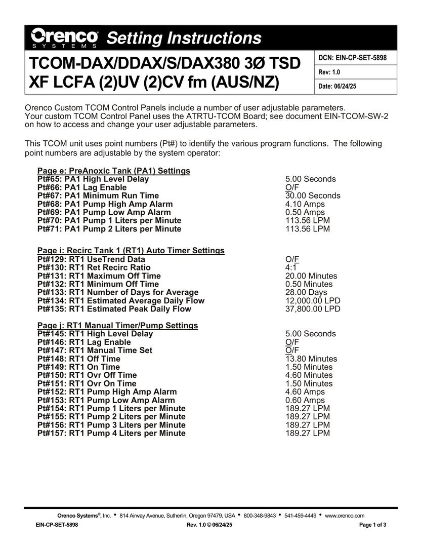
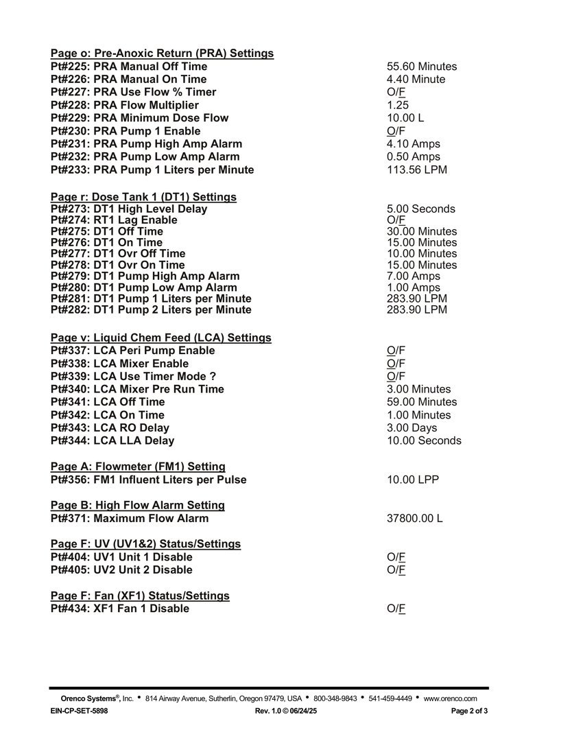
The same Pt# setpoints appear on the web, Viewer, and HMI. Baseline values from Appendix 14 (EIN-CP-SET-5898) — confirm live values before troubleshooting. Operator use cases for the web screens: 3.2.17.
Page e — Pre-Anoxic Tank (PA1)
Use case. When the primary tanks run high or a transfer pump pages, Page e is the duplex rulebook: how long a high float must stay true before the plant reacts, whether the lag pump can help, how short a run is allowed, and what amp band means “healthy.” Wrong LPM here does not move more water — it only lies about how much moved.
| Pt# | Parameter | Baseline | What it does |
|---|---|---|---|
| 65 | High Level Delay | 5.00 s | Debounce before high-level response |
| 66 | Lag Enable | O/F | Lag pump assist |
| 67 | Minimum Run Time | 30.00 s | Anti short-cycle |
| 68–69 | High / Low Amp Alarm | 4.10 / 0.50 A | Electrical windows |
| 70–71 | Pump 1 / 2 LPM | 113.56 each | Flow calibration |
Page i — Recirc Tank Auto Timer (RT1)
Use case. This is the brain of AdvanTex recirculation under normal conditions. Estimated Flow uses design LPD until enough history exists; Trend then drives off times from real averages. The 4:1 ret recirc ratio is the treatment intensity knob — change it only with Orenco / ENVR. Max/min off-time clamps stop the timer from sitting forever idle or hammering the beds.
| Pt# | Parameter | Baseline | What it does |
|---|---|---|---|
| 129 | Use Trend Data | O/F | On = Trend; Off = Estimated Flow |
| 130 | Ret Recirc Ratio | 4:1 | Recirc vs forward flow |
| 131–132 | Max / Min Off Time | 20.00 / 0.50 min | Idle-time clamps |
| 133 | Days for Average | 28 | Rolling average window |
| 134–135 | Est Avg / Peak Daily Flow | 12,000 / 37,800 LPD | Estimated Flow design flows |
Page j — Recirc Tank Manual Timer / Pumps (RT1)
Use case. Manual Time Set is the emergency override: when On, the fixed on/off times below replace Auto/Trend. Leave it Off unless ENVR is running a controlled trial. The rest of the page is pump protection (amps) and per-pump LPM so four recirc pumps report fair share of the work.
| Pt# | Parameter | Baseline | What it does |
|---|---|---|---|
| 145–146 | High Level Delay / Lag | 5.00 s / O/F | Level / lag |
| 147 | Manual Time Set | O/F | On overrides Auto/Trend — leave Off unless directed |
| 148–151 | Off / On / Ovr Off / Ovr On | 13.80 / 1.50 / 4.60 / 1.50 min | Manual dose timing |
| 152–153 | High / Low Amp Alarm | 4.60 / 0.60 A | Amp windows |
| 154–157 | Pump 1–4 LPM | 189.27 each | Per-pump calibration |
Page o — Pre-Anoxic Return (PRA)
Use case. Return filtrate closes the nitrogen loop. If Pump 1 Enable is left Off after maintenance, the plant can look “fine” on recirc Status while return is dead. On/off times and flow-paced options set how aggressively filtrate comes back; amp windows catch a seized or dry return pump.
| Pt# | Parameter | Baseline | What it does |
|---|---|---|---|
| 225–226 | Manual Off / On | 55.60 / 4.40 min | Time-dose cycle |
| 227–229 | Flow % / multiplier / min dose | O/F · 1.25 · 10 L | Flow-paced options |
| 230 | Pump 1 Enable | O/F | Enable return pump |
| 231–233 | Amp alarms / LPM | 4.10 / 0.50 A · 113.56 LPM | Protection / calibration |
Page r — Dose Tank / Discharge (DT1)
Use case. These timers decide when treated water leaves toward the LAA / RWS. After wet weather, high storage, or an irrigation complaint, Page r (with DT1 Status) tells you whether the plant is calling discharge and on what cycle. Amp windows are wider (2 hp pumps); LPM feeds FlowData used in monthly reporting.
| Pt# | Parameter | Baseline | What it does |
|---|---|---|---|
| 273–274 | High Level Delay / Lag | 5.00 s / O/F | Level logic |
| 275–278 | Off / On / Ovr Off / Ovr On | 30 / 15 / 10 / 15 min | Discharge timing |
| 279–280 | High / Low Amp Alarm | 7.00 / 1.00 A | 2 hp windows |
| 281–282 | Pump 1 / 2 LPM | 283.90 each | Discharge calibration |
Page v — Liquid Chem Feed (LCA)
Use case. Alkalinity feed is easy to forget until lab results slip. Peri and Mixer Enable are master switches; Mixer Pre Run stirs before the peri doses; timer or flow-pace chooses the strategy. After a tote change or isolation for work, confirm both enables are back On before leaving the control room.
| Pt# | Parameter | Baseline | What it does |
|---|---|---|---|
| 337–338 | Peri / Mixer Enable | O/F | Master enables |
| 339 | Use Timer Mode? | O/F | Timer vs flow-pace |
| 340 | Mixer Pre Run | 3.00 min | Mixer before peri |
| 341–342 | Off / On | 59.00 / 1.00 min | Timer cycle |
| 343–344 | RO Delay / LLA Delay | 3.00 days / 10 s | Float delays |
Pages A / B / F / H — Flow, UV, Fan, Alarms
Use case. Page A turns meter pulses into litres — get LPP wrong and every flow figure is fiction. Page B is the daily high-flow trip (37,800 L). Page F is disinfection and AX ventilation: UV Disable does not stop pumps, so a disabled UV is a quality problem, not a hydraulic lockout. Page H explains the quiet plant: horns can wait 120 min, pages every 30 min — so “no siren yet” does not mean “no alarm.”
| Pt# | Parameter | Baseline | What it does |
|---|---|---|---|
| 356 | FM1 Liters per Pulse | 10.00 LPP | Pulse → litres |
| 371 | Maximum Flow Alarm | 37,800 L | High-flow alarm |
| 404–405 | UV1 / UV2 Disable | O/F | Independent UV enable |
| 434 | XF1 Fan 1 Disable | O/F | AX fan enable |
| 465 | Audible Alarm Activate Delay | 120 min | Horn delay |
| 466 | Audible Alarm ReActivate Delay | 720 min | Re-sound interval |
| 467 | Page Interval | 30 min | Remote notify spacing |
| 468 | Current Alarm Delay | 20 s | Current-sensor debounce |
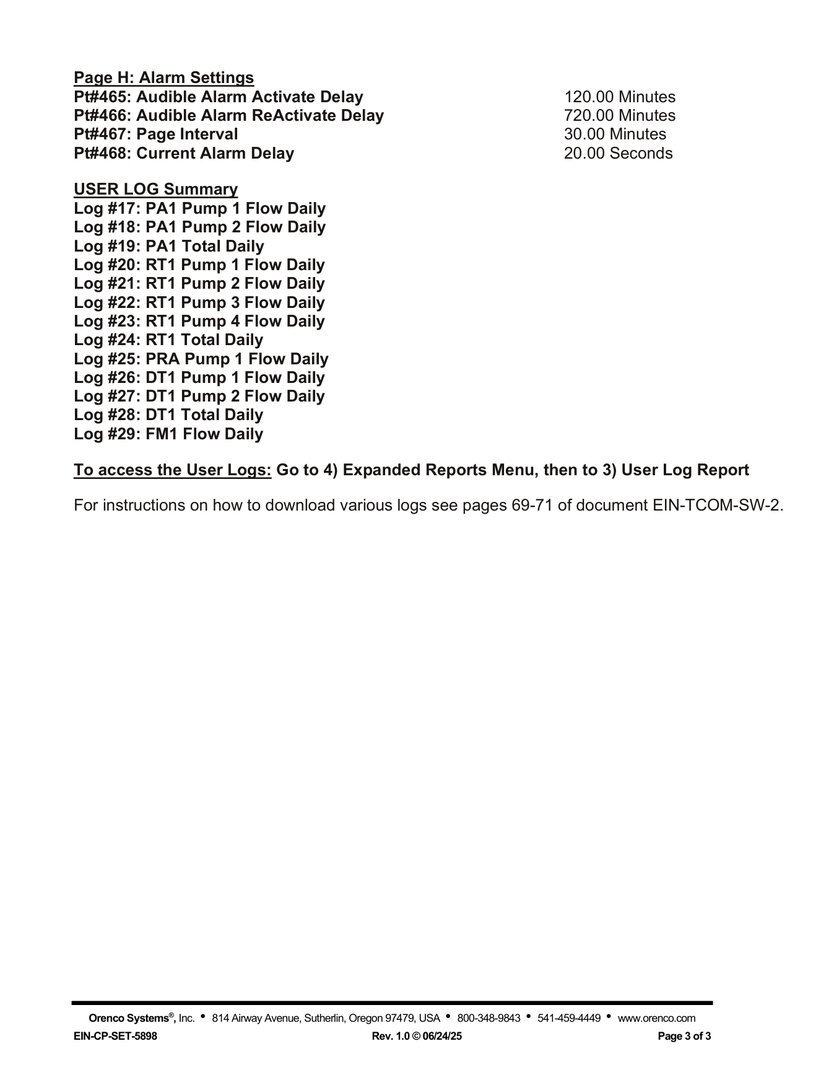
User Logs
| Log # | Content |
|---|---|
| 17–19 | PA1 Pump 1 / Pump 2 / Total Daily |
| 20–24 | RT1 Pump 1–4 / Total Daily |
| 25 | PRA Pump 1 Flow Daily |
| 26–28 | DT1 Pump 1 / Pump 2 / Total Daily |
| 29 | FM1 Flow Daily |
Contacts
| Role | Contact |
|---|---|
| Remote monitoring / T-COM | ENVR Solutions — Matt McKennariey — 0402 524 033 · m.mckennariey@envr.com.au |
| Site caretaker | Lakeside Upkeep and Tech (Tim Earl — 0417 892 281) — 6.3 |
| Local electrician | Top End Electrical — Liam Kuhl — 8945 5684 / 0438 486 603 |
| AdvanTex manufacturer | Orenco Systems — +1 (541) 537-0049 · bhensley@orenco.com |
Version Control
| Version | Date | Description |
|---|---|---|
| 1.0 | 2026-10-18 | Initial combined T-COM page |
| 1.1 | 2026-10-18 | Per-page descriptions and O&M figures |
| 2.0 | 2026-10-18 | Split into overview + web / Viewer / local HMI pages |
| 3.0 | 2026-10-18 | Operator use cases for each point-page group |
| 3.1 | 2026-10-20 | Photo of Orenco panel door with LCD Main Menu |
| 3.2 | 2026-10-20 | Photo of AOH switches; door legend AUTO/OFF/MAN |
| 3.3 | 2026-10-20 | Style guide compliance — Title Case headings and note title |
Next Review Date: 2027-04-20