3.1.3 Chlorine Dosing System
Chlorine Dosing System Documentation
Overview
This document outlines the installation, operation, and maintenance procedures for the chlorine dosing system located at the Lake Bennett Estate bore infrastructure. It includes a full breakdown of the system’s components, control methodology, safety considerations, and troubleshooting steps.
Table of Contents
- System Description
- Component Overview
- Operating Principles
- Maintenance Procedures
- Troubleshooting
- Safety and Containment
- Chlorine Refill Procedure
- Appendix A – Equipment Specifications
System Description
The chlorine injection system is an inline dosing mechanism connected to the bore supply line. It is triggered by flow-based pulse signals generated by a mechanical water meter. The system is designed to deliver precise chlorine dosing proportional to water usage, ensuring effective water treatment for potable and non-potable applications.
Component Overview
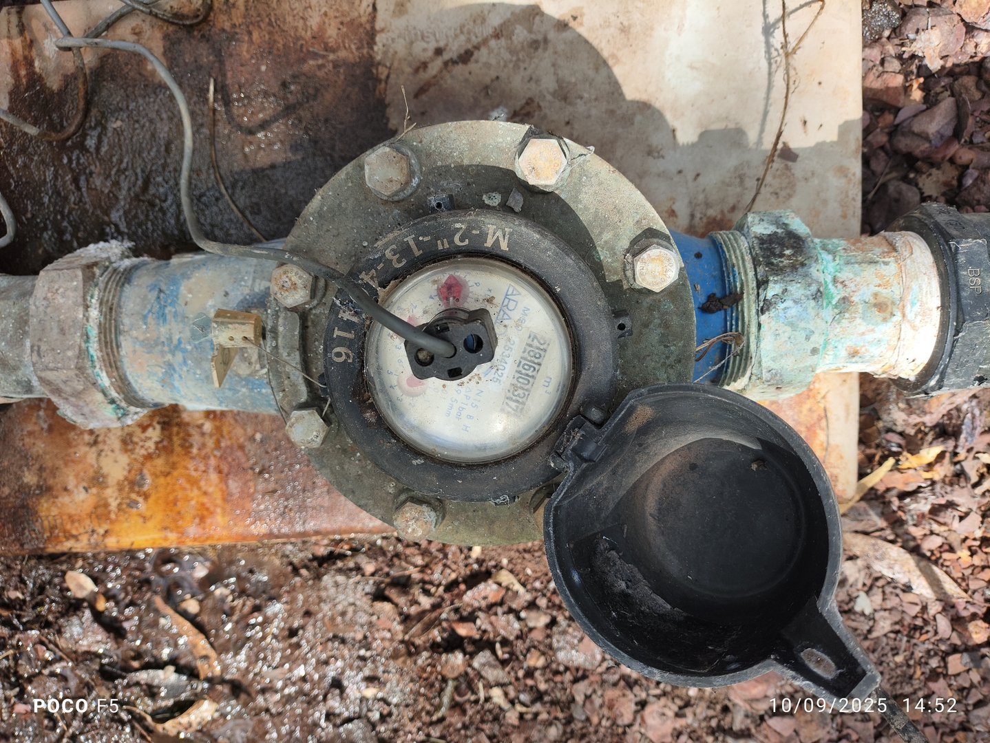
Water Meter and Pulse Sensor
A mechanical inline water meter generates electrical pulses relative to flow. These pulses are transmitted via low-voltage cable to the dosing pump located inside the chlorination shed.
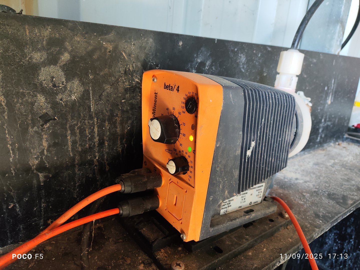
Dosing Pump
A Prominent Beta 4 chlorine metering pump receives the pulse signal and dispenses chlorine solution accordingly. Key features include:
- Serial No.: 371815956
- Adjustable dosing rate (0–100%) via front panel knob
- Pulse source selector (internal/external)
- Pulse ratio for higher flow accuracy
- Power: 240V AC from GPO in chlorination shed
- Continuous mode for priming or bleeding
Manufacturer Resources: - Prominent Website - Beta 4 Operating Instructions Manual
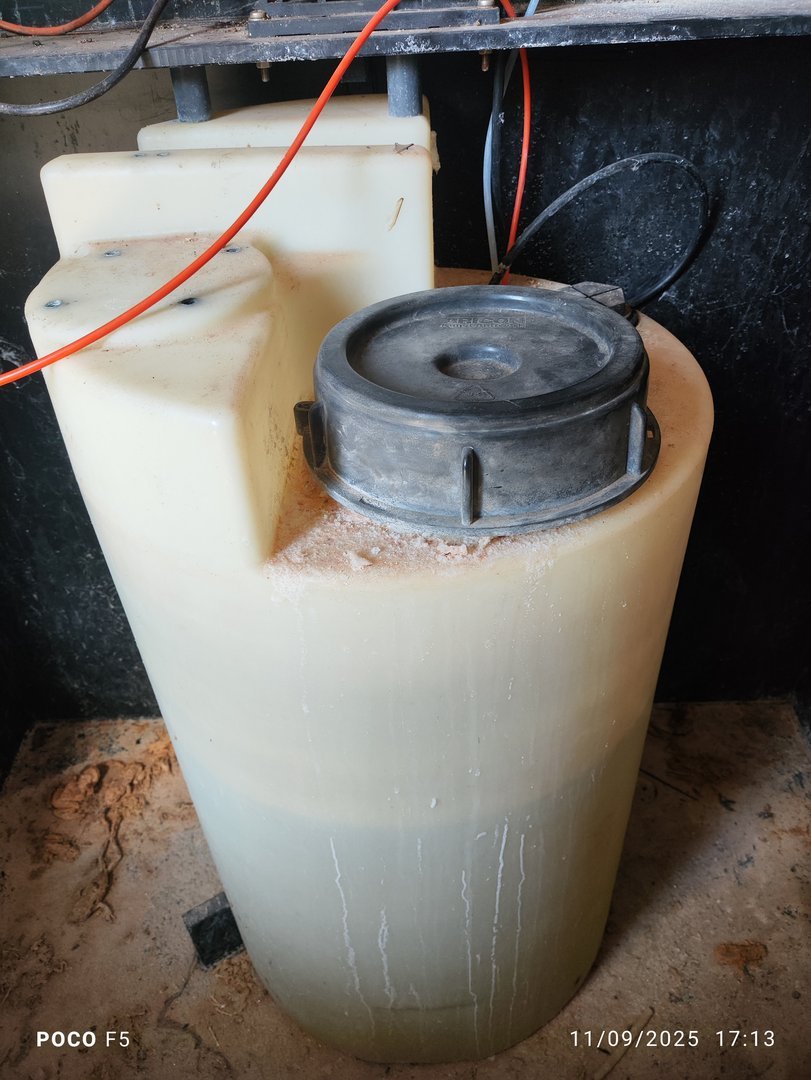
Chlorine Storage Tank
- Capacity: 100L UV-resistant plastic tank
- Features: Low-level float sensor cuts power to pump below ~10L to prevent dry running
- Filling: Manual via sealed top access cap
- Positioned within a bunded spill containment enclosure
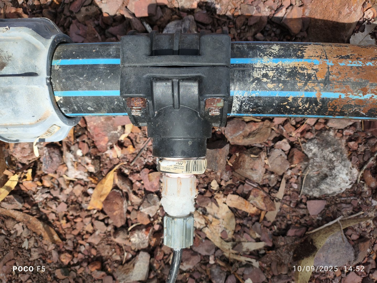
Injection Point
Chlorine is injected into the bore main just downstream of the flow meter. Tubing is secured and rated for high-pressure delivery.
Operating Principles
- Water flows through the mechanical meter, generating electrical pulses.
- Each pulse is received by the Beta 4 dosing pump.
- Based on the pulse ratio and dosage rate, chlorine is injected into the bore line.
- The system operates passively—chlorine delivery is fully synchronized with bore output volume.
Maintenance Procedures
- Daly
- Confirm chlorine level is above the 10L cutoff
- Check for signs of air in dosing lines
-
Confirm pump is responding to pulses
-
Weekly
- Test output concentration using water sampling
-
Visually inspect tubing and injection points
-
Monthly
- Check operation of the low-level sensor
-
Flush or replace any clogged sections of line
-
Quarterly
- Verify bund tank is clean and free of residues
Troubleshooting
Problem: Inadequate Chlorine Output
Symptoms:
- Low chlorine residual detected during routine testing
- Dosing pump appears to run, but injection is weak or inconsistent
Likely Cause:
- Air trapped in suction or discharge lines
Bleeding Procedure
Safety Warning
Always wear full PPE including gloves and a face shield.
-
Confirm Chlorine Level
Open the top cap and visually inspect fluid level. If below 10L, refill (see Refill Procedure). -
Set Pump to Manual Prime
- Set dosing knob to 100%
- Set pulse source to “Internal”
-
Set pulse rate to 100% (continuous operation)
-
Bleed the Output Line
- Carefully disconnect the injection line from the bore water main end
- Allow chlorine to pulse through until all air is purged
-
Observe strong, consistent pulses without bubbles
-
Return to Normal Operation
- Reconnect output line securely
- Set pulse source back to “External”
-
Adjust dosing knob to target setting (e.g. 25%)
-
Verify Operation
- Observe LED pulse indicators (double flash confirms external sync)
- Sample water post-injection and verify chlorine level
Safety and Containment
- The entire dosing system is mounted within a bunded containment enclosure to mitigate spills or leaks.
- Only trained personnel should handle chlorine. A full PPE kit (face shield, gloves, long sleeves) must be worn when:
- Refilling chlorine
- Bleeding the system
-
Performing maintenance
-
Maintain clear access to the spill containment area for inspection and cleaning.
- Ensure the chlorination shed remains well-ventilated at all times.
Chlorine Refill Procedure
-
Wear PPE
Face shield, gloves, and long-sleeved protective clothing are mandatory. -
Open Fill Cap
Unscrew the large black lid atop the chlorine tank. -
Add Chlorine
Pour chlorine slowly from a sealed 20L drum supplied by Harvey Distributors. Top up to full capacity (100L). -
Secure Lid
Replace and tighten the tank cap to prevent evaporation and contamination. -
Inspect for Spills
Check bund for drips or overflow. Rinse and dilute if necessary.
Recommended Product
Sodium Hypochlorite 12.5% (20L drums)
Supplier: Harvey Distributors
SDS and Product Datasheet: [Insert link here]
Appendix A – Equipment Specifications
| Component | Model | Notes |
|---|---|---|
| Dosing Pump | Beta 4 | Ser. No. 371815956, External pulse input |
| Chlorine Tank | 100L HDPE | Bunded, with float switch |
| Water Meter | Mechanical Inline | Pulse output (2:1 ratio) |
| Tubing | Chemical-rated | Rated for chlorine and bore pressure |
| Power Supply | 240V AC | GPO in chlorination shed |
Version Control
| Version | Date | Description |
|---|---|---|
| 1.0 | 2025-10-06 | Initial Release |
Next Review Date: 2026-04-06