3.2.8 Effluent Disposal
This section details the Land Application Areas (LAA) for disposal of Class A recycled water via subsurface dripline irrigation, based on the LBC OWMS O&M Manual V1.1.
Legacy System Decommissioned
The previous Land Application Area — concrete distribution box feeding four plastic tunnel trenches (~140 m total) — has been decommissioned and replaced by the subsurface dripline irrigation system described below.
System Overview
Treated effluent from the WWTP is reused as a watering resource and irrigated via subsurface driplines installed across two designated irrigation areas. Distribution valves ensure even distribution of recycled effluent throughout the soil profile, eliminating the risk of over-saturation and runoff.
Manual isolation and automatic solenoids for the absorption areas are on the control-room distribution manifold.
| Parameter | Value |
|---|---|
| Technology | Netafim Bioline 17 pressure-compensating dripline (Thinkwater NT) |
| Pipework colour | Lilac (permanently coloured, per recycled water standards) |
| Design total area | 9,425 m² (plan cover sheet) |
| Operational area | 7,620 m² (see breakdown below) |
| Design Loading Rate | 3 mm/day DLR = 22,860 L/day allowable discharge |
| Daily max discharge (programmed) | 28,600 L (user-adjustable default in discharge tank logic) |
Irrigation Areas
Irrigation Area 1
| Item | Detail |
|---|---|
| Total Area | 1,386 m² |
| Configuration | Operates as one singular area |
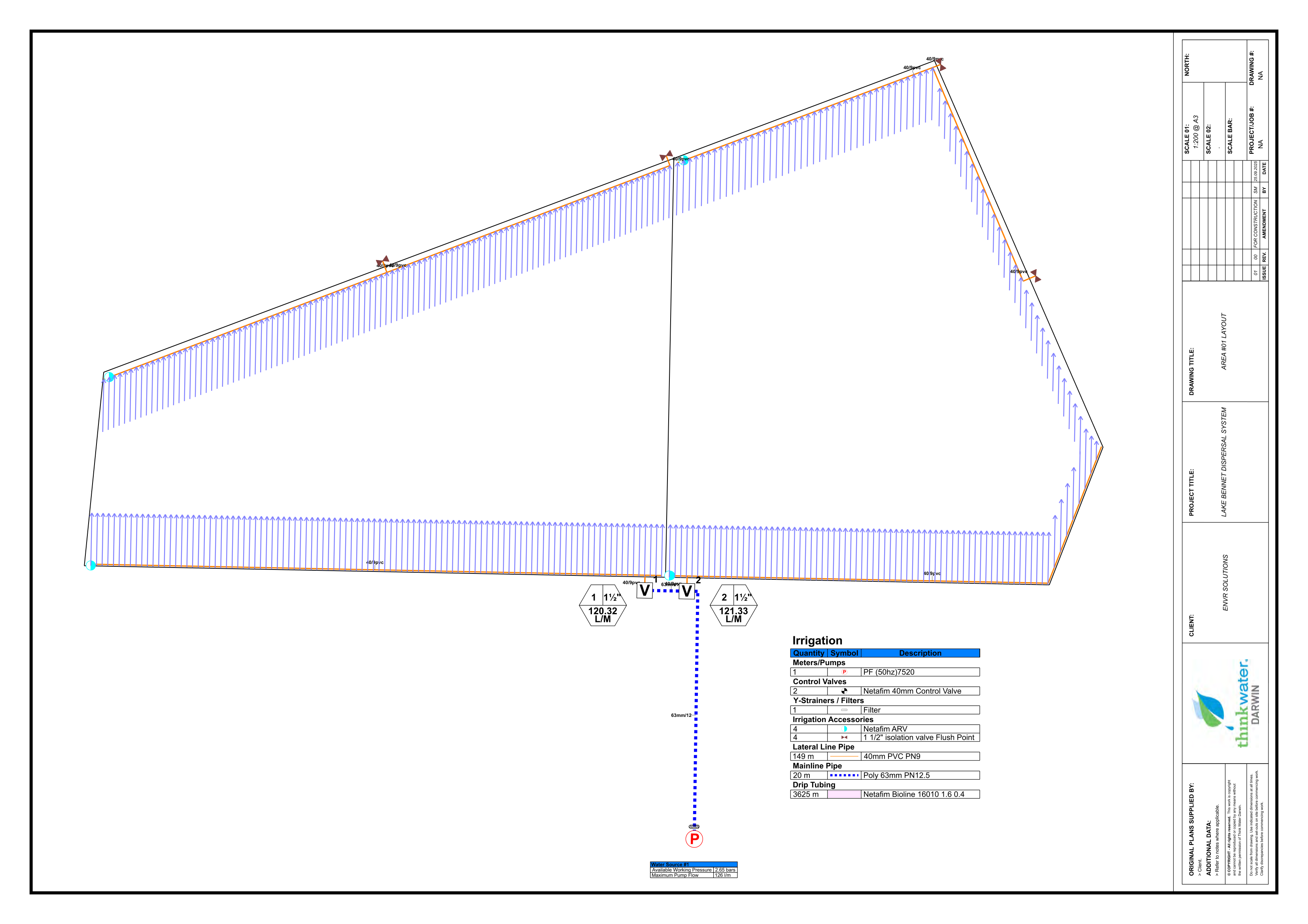
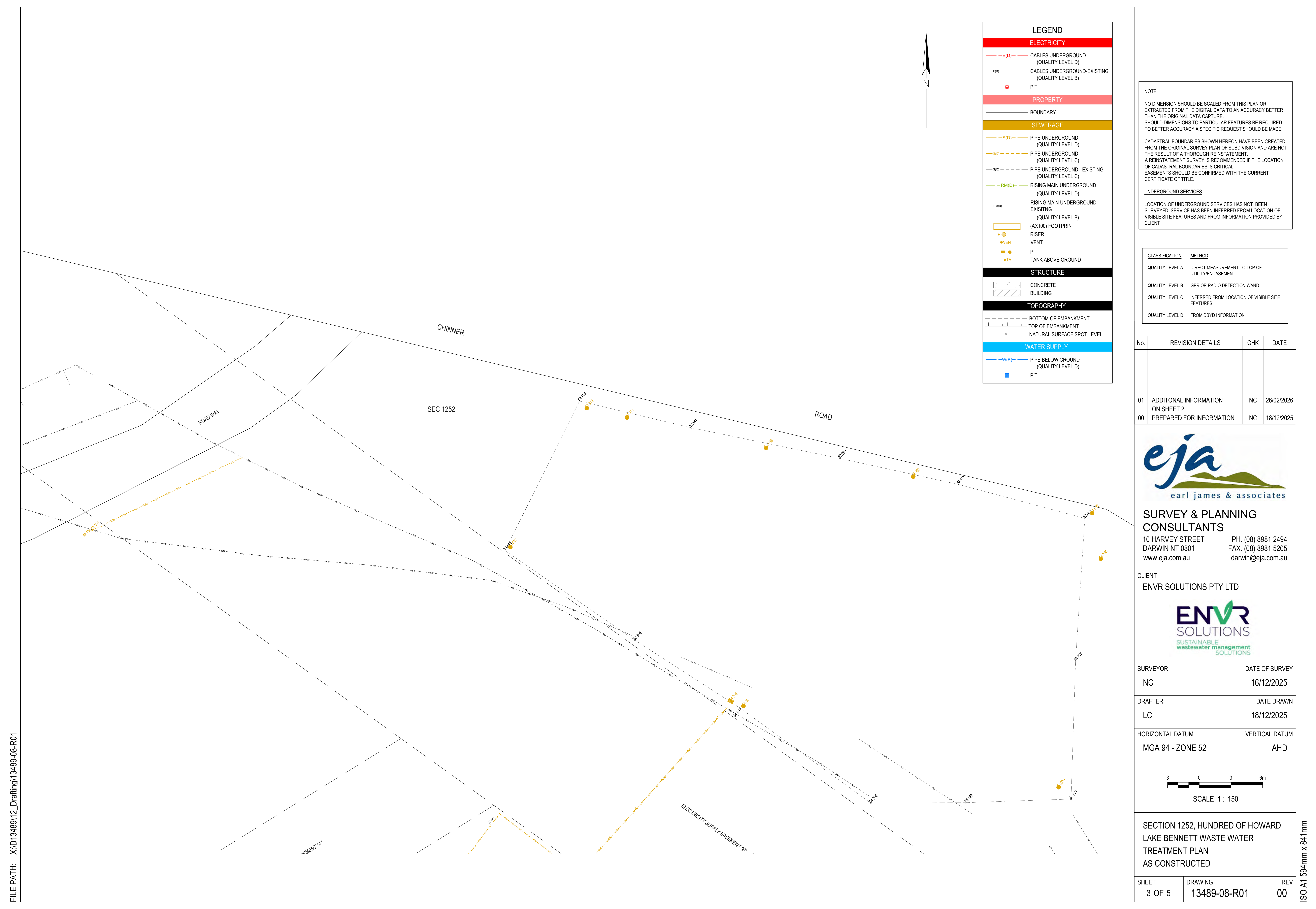
| Drawings | Thinkwater AREA #01 (LAA A); as-constructed Sheet 3 of 5 |
| Site Location | Larger singular field north-east of Area 2, nearer Chinner Road, immediately downslope of the WWTP |
| Potable Makeup | Purple in-ground valve box beside the control room — see 3.2.13 Potable Water Valve Boxes |

Flow Direction on AREA #01 Design
On the Thinkwater layout, effluent enters from the southern edge (valves and pump) and distributes upslope through the dripline grid.
Irrigation Area 2
| Item | Detail |
|---|---|
| Total Area | 6,234 m² |
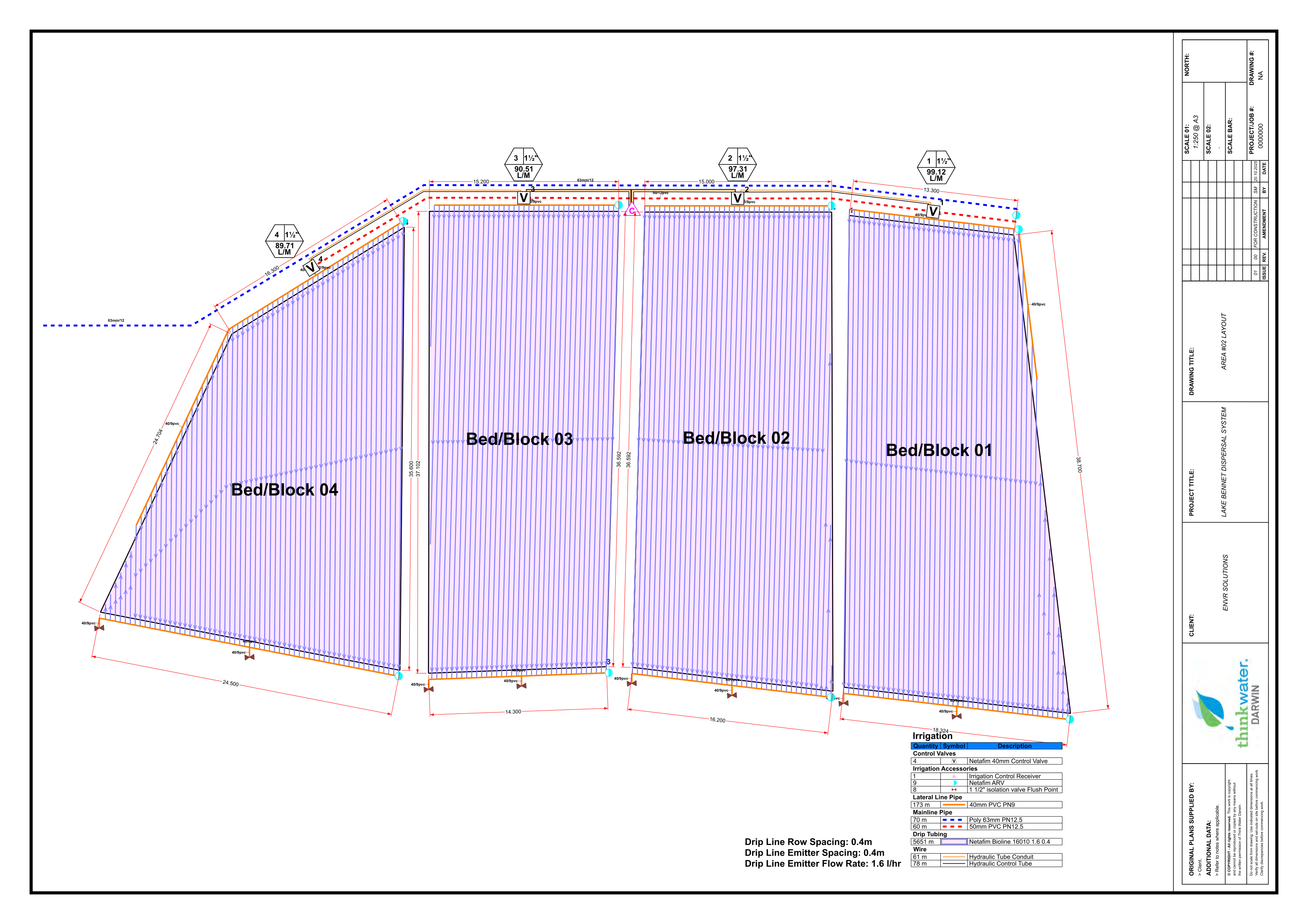
| Configuration | Separated into 4 sub-areas controlled via individual solenoid valves |
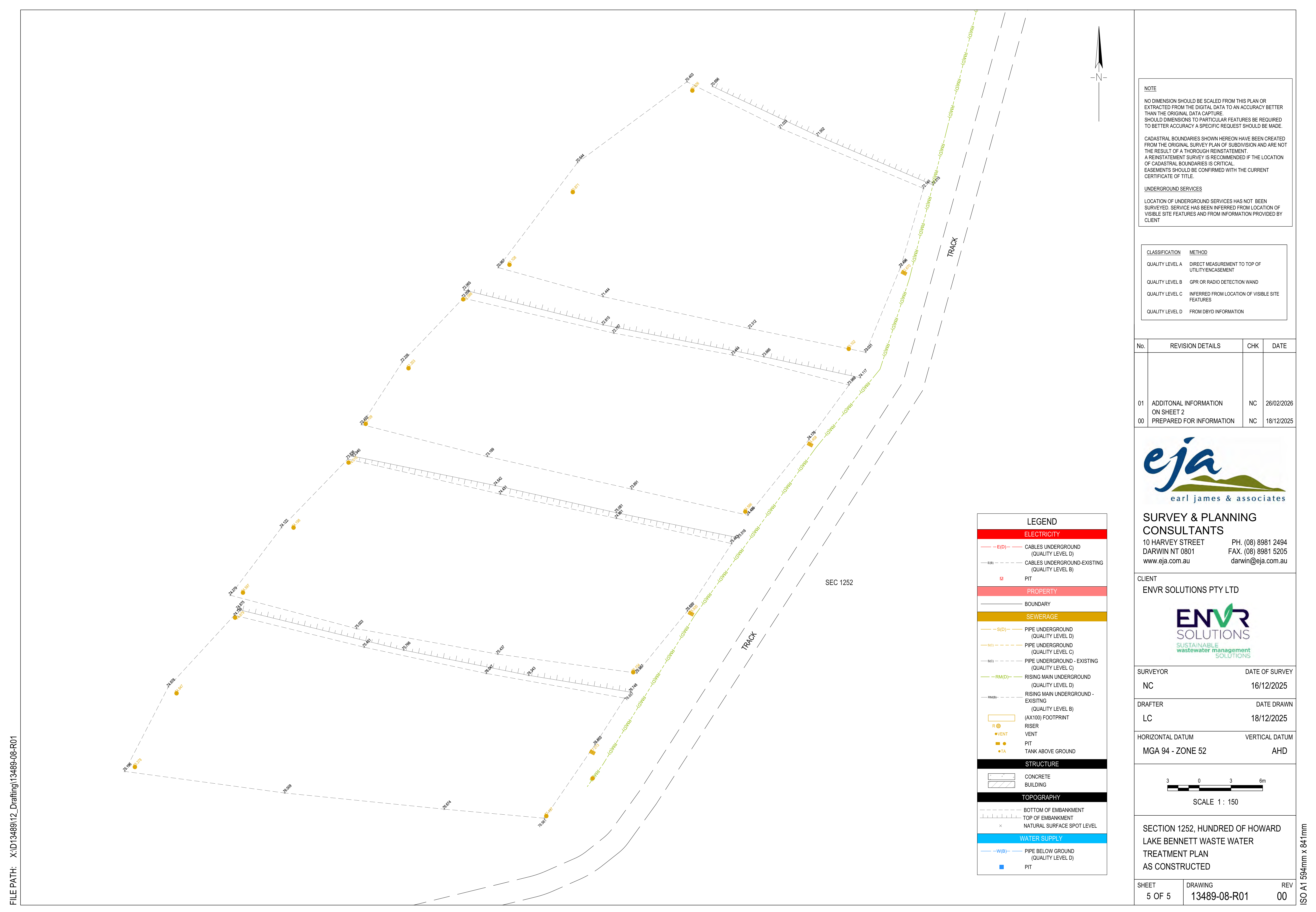
| Drawings | Thinkwater AREA #02 (LAA B); as-constructed Sheet 5 of 5 |
| Site Location | Four terraced beds on the hill south of the WWTP |

Bed Numbering on AREA #02 Design
Sub-areas on the Thinkwater drawing are numbered Bed/Block 01–04 from right to left (east to west on the plan). Each bed is served by its own solenoid valve.
Combined Total
7,620 m² operational irrigation area.
Area Discrepancy
The design cover sheet references 9,425 m² as the total permitted disposal area. The operational breakdown (1,386 + 6,234 m²) sums to 7,620 m². The design total includes the full permitted disposal area allocation.
Signage and Identification
Prominent warning signs are displayed in the vicinity of all irrigation zones:
RECYCLED WATER BEING USED — AVOID CONTACT
All pipelines and fittings associated with the irrigation zones are distinctly and permanently coloured lilac.
Environmental Benefits
Subsurface dripline irrigation:
- Evenly distributes water throughout the soil profile, eliminating over-saturation and runoff
- Maximises evapotranspiration from vegetation planted within the garden beds
- Makes beneficial residual nutrients available to plant root-mass within the rhizosphere
- Prevents runoff and potential contamination of adjacent aquatic habitats (Lake Bennett)
Maintenance
Routine Tasks
| Task | Detail |
|---|---|
| Mowing/slashing | Periodic, as required |
| Weed control | Keep all irrigation areas clear of weeds — careful application of wick-type herbicides or mechanical means |
| Ponding checks | Check for pooling or ponding caused by possible dripline or pipework breakages; repair as necessary |
| Soil health | Twice-yearly checks of soil pH and conductivity |
| Low-occupancy watering | Deploy potable water irrigation during periods of low occupancy and/or when turf shows signs of heat stress or water deficiency — Absorption Area 1 via the purple valve box beside the control room |
Performance Indicators
- Turf is healthy and actively growing
- All irrigation areas display even coverage of turf with no lines or die-off
- Weeds are not present
- Irrigation areas are mowed and tidy
Maintenance Program (Table 1)
| Item | Task | Action | Frequency | Responsible |
|---|---|---|---|---|
| 3 | Mowing and groundskeeping | Irrigation areas | Weekly (or as required) | Site Caretaker |
| 8 | Turf health assessment | Check for pests, diseases, and growth inhibitors | Quarterly | ENVR |
| 20 | Leak and pooling inspection | Inspect all irrigation areas; repair as necessary | Quarterly | ENVR |
See 3.2.15 O&M and Contingency for the full maintenance program.
Wet Weather and Storage
When irrigation is not possible due to prolonged wet weather, treated effluent is diverted to the 3.2.14 Recycled Water Storage. If storage reaches capacity, engage McMinns Pumping Systems (0408 895 171) for licensed pump-out.
Version Control
| Version | Date | Description |
|---|---|---|
| 1.0 | 2025-10-06 | Initial Release (legacy trench LAA) |
| 2.0 | 2026-06-22 | Rewritten for subsurface dripline irrigation per O&M Manual V1.1 |
| 2.0.1 | 2026-06-22 | Added LAA Area A and B design and layout diagrams |
| 2.0.2 | 2026-06-22 | Corrected area presentation order and layout/design sequence |
| 2.0.3 | 2026-06-22 | Corrected irrigation area sizes, configurations, and site locations |
| 2.1 | 2026-08-30 | Linked control-room manifold for LAA isolation and solenoids |
| 2.2 | 2026-08-30 | Photo of Absorption Area A |
| 2.3 | 2026-08-30 | Photo of Absorption Area B |
| 2.4 | 2026-08-30 | Linked purple potable-water valve box for Absorption Area 1 |
Next Review Date: 2026-12-22