3.2.13 Disinfection & Polishing
This section details the microfiltration, UV disinfection, and chlorine dosing systems that polish treated effluent to Class A recycled water standards. Based on the LBC OWMS O&M Manual V1.1.
Distinct from Bore Chlorine System
This chlorine dosing system is part of the WWTP and is separate from the 3.1.3 Chlorine Dosing used for potable water treatment.
Treatment Sequence
Treated effluent from the discharge tank passes through the control room in this order:
- Microfiltration — polishes remaining suspended solids
- UV disinfection — primary disinfection
- Chlorine dosing — secondary disinfection
- Distribution — to RWS tanks or LAA irrigation areas
Microfiltration
| Item | Detail |
|---|---|
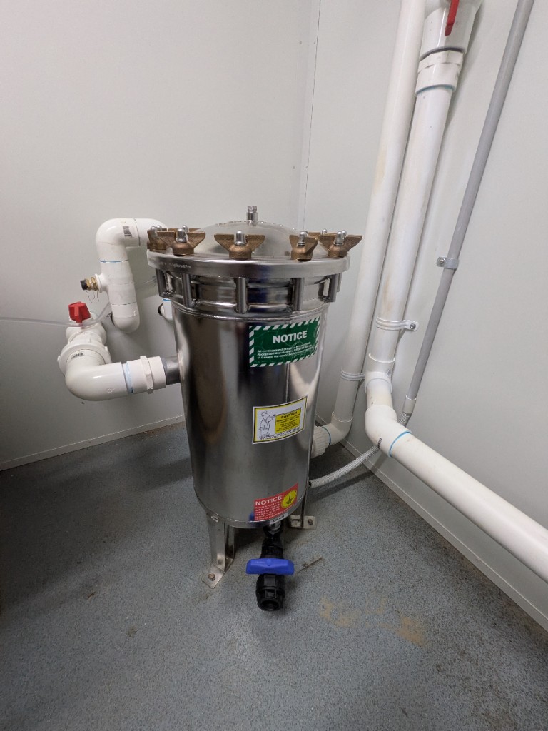
| Housing | Harmsco HUR 90 HP (Orenco) |
| Filters | HC/90-5 cartridge filters (Orenco) |
| Purpose | Achieve TSS target of <10 mg/L; ensure lowest turbidity for optimum UV disinfection |
| Position | Upstream of UV disinfection system |
| Isolation | Red-handled ball valves on the inlet/outlet PVC |
| Flush | Blue-handled valve on the black drain from the base of the housing |
Maintenance
| Task | Frequency | Responsible |
|---|---|---|
| Remove and clean filter cartridge | Quarterly | ENVR |
UV Disinfection
| Item | Detail |
|---|---|
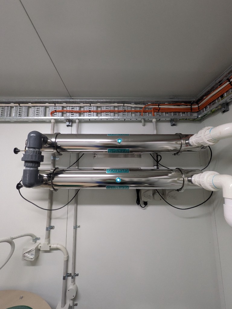
| Model | Sanitron S5000C (Orenco) |
| Quantity | 2 units |
| Power | 220 V 1Ø, 0.64 A each |
| Control | Independent enable/disable points on T-COM panel |
| Fault behaviour | UV fault does not disable any pump |
| Mounting | Two Sanitron canisters stacked on the control-room wall; lamp-status indicators on each unit |
Maintenance
| Task | Frequency | Responsible |
|---|---|---|
| Clean UV glass sleeves via internal wiper mechanism | Quarterly | ENVR |
| Replace UV lamps | Annually | ENVR |
Chlorine Dosing
| Item | Detail |
|---|---|
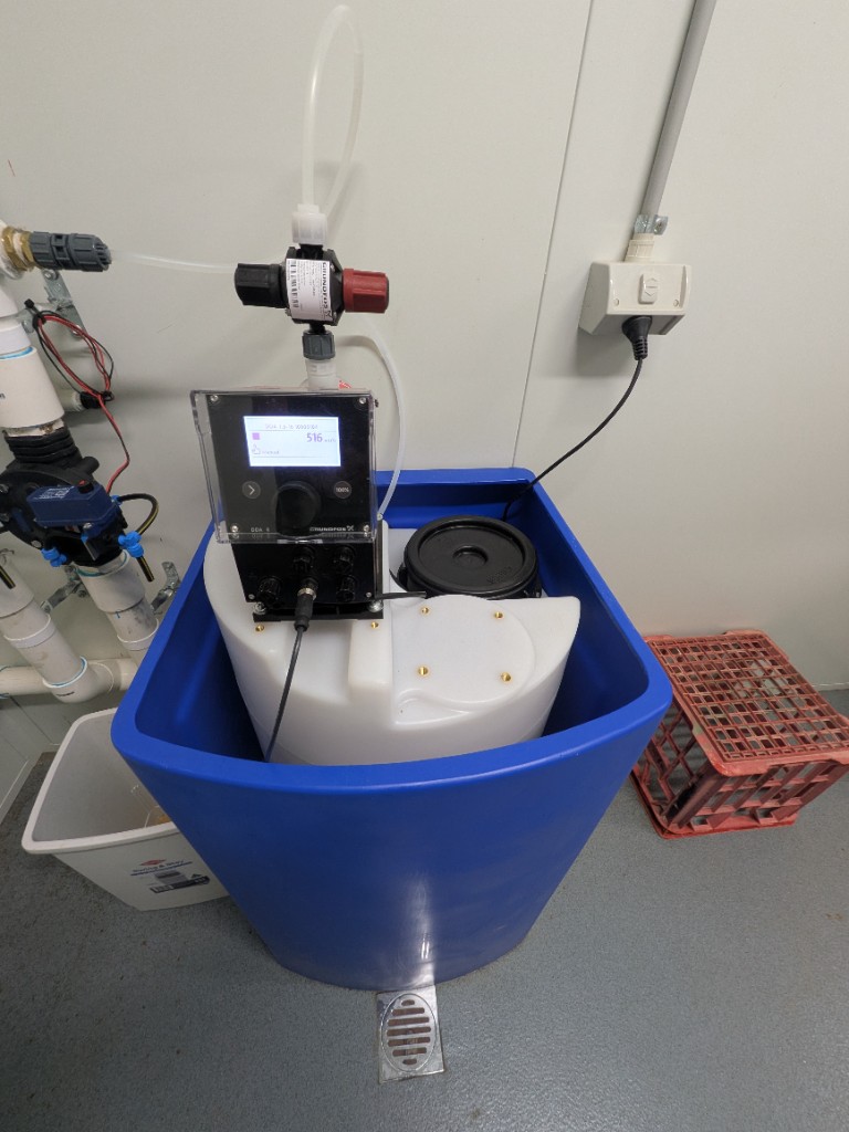
| System | Grundfos Dosing Station DDA 7.5-16 AR (1 L02 P1 02) |
| Supplier | Thinkwater NT |
| Location | Climate-controlled WWTP control room (20 ft container) |
| Pump | Grundfos SMART Digital DDA, mounted on the inner tank lid |
| Inner Tank | White plastic reservoir with black screw-top lid |
| Containment | Blue square bund around the inner tank; floor drain immediately in front of the station |
Chlorine dosing provides secondary disinfection after UV treatment. Ample chlorine supply must always be available on site.
Injection Point
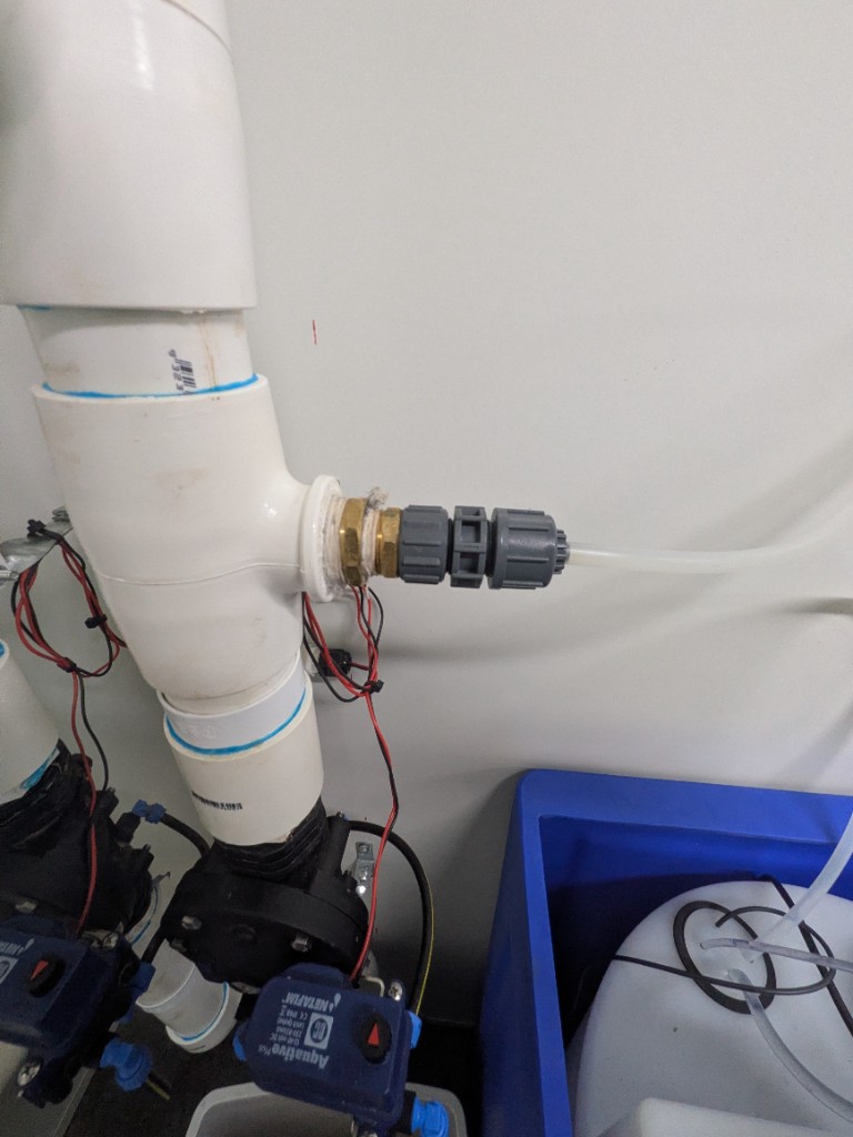
Chlorine solution is injected into the treated-effluent line on the control-room wall, downstream of the dosing station.
| Item | Detail |
|---|---|
| Injection | Chemical-rated tube into a PVC T on the vertical effluent pipe |
| Fittings | Brass adapter and grey compression fittings on the side-feed |
| Manifold | Same wall assembly as the distribution manifold; Netafim Aquative Plus solenoids below the T |
Chlorine Storage Safety
Chemical Storage
Chlorine and all chemicals must be stored in appropriately bunded and signed areas with relevant safety information and MSDS sheets readily available.
See 3.2.15 Safety Guidelines for full PPE and hazard requirements.
Class A Discharge Targets
| Parameter | Target |
|---|---|
| E. coli | ≤ 10 CFU/100 mL (max) |
| BOD | ≤ 30 mg/L (max) |
| TSS | ≤ 20 mg/L (max) |
| TN | ≤ 60 mg/L (avg) |
| TP | ≤ 20 mg/L (avg) |
| pH | 6–9 |
Contingency — Declining Disinfection Performance
E. Coli Failure
| Control |
|---|
| Ensure ample chlorine supply on site |
| Confirm chlorine doser operation |
| Maintain chlorine dosing per manufacturer requirements |
| Confirm UV disinfection system operation |
| Clean UV glass sleeves using manual wiper |
| Replace UV bulbs annually |
TSS Failure
| Control |
|---|
| Clean out microfiltration cartridge |
| Ensure AdvanTex ventilation assembly operational |
| Review and adjust recirculation ratios |
| Ensure primary tank effluent filters in place and functional |
| Manage sludge/scum in septic tanks to prevent carryover |
See 3.2.15 Contingency Plans for full declining water quality response procedures.
Control Room
The microfiltration unit, UV system, chlorine dosing, alkalinity mixer/dosing tank, flow meter, and T-COM control panel are installed inside a secure, climate-controlled 20 ft shipping container (repurposed MAC Water Treatment Plant container, fitted out by SCF Containers Berrimah).
The control room includes:
- Potable water supply with backflow prevention (see below)
- Sample collection tap (see below)
- Distribution manifold to LAA and RWS (see below)
- Mechanical flow meter (see below)
- Alkalinity dosing tank and mixer — see 3.2.11 Primary Treatment
- WiFi router and outdoor transmitter for T-COM and contractor internet (see below)
- Power distribution board (see below)
- Electrical pit behind the control room (see below)
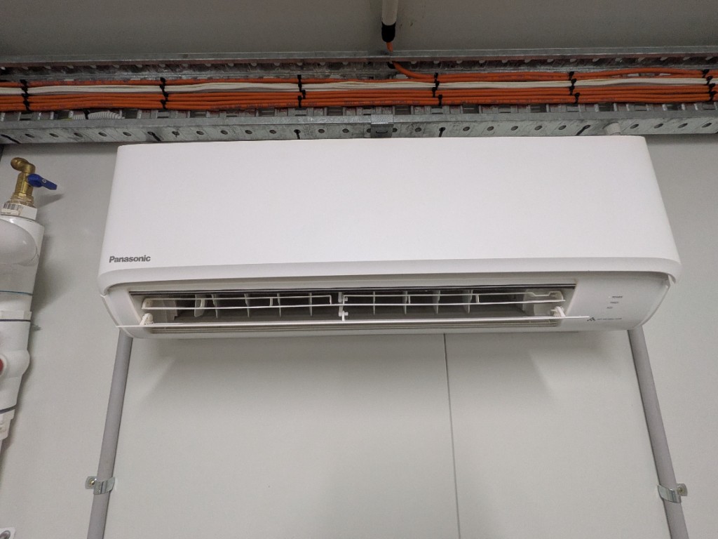
- Air conditioning indoor unit (see below)
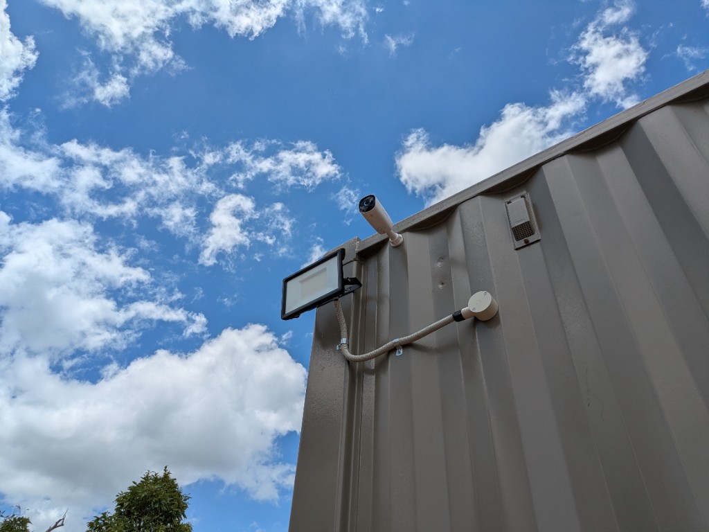
- Floodlight and security camera on the container (see below)
- Work bench
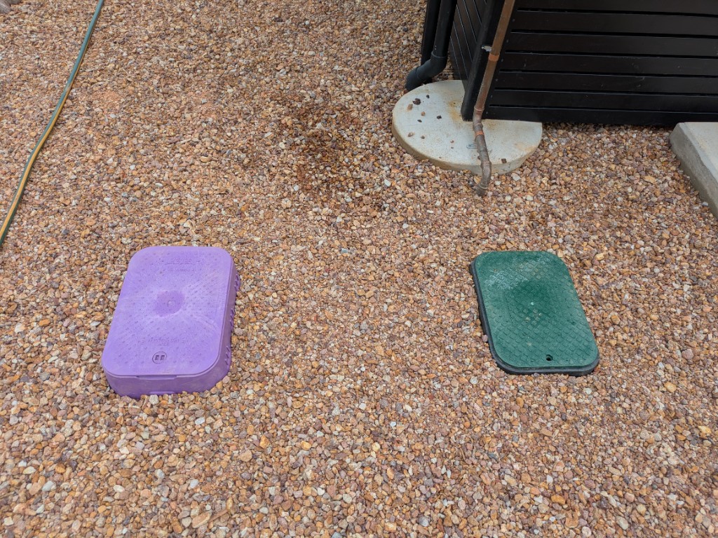
Potable Water Valve Boxes
Two in-ground valve boxes in the gravel beside the control-room container.
| Item | Detail |
|---|---|
| Purple box | Valve allowing potable water into Absorption Area 1 (the field at the bottom of the hill) — used for low-occupancy / turf makeup watering; see 3.2.8 Irrigation Area 1 |
| Green box | Isolation valve for potable water to the control room |
Sample Collection Tap
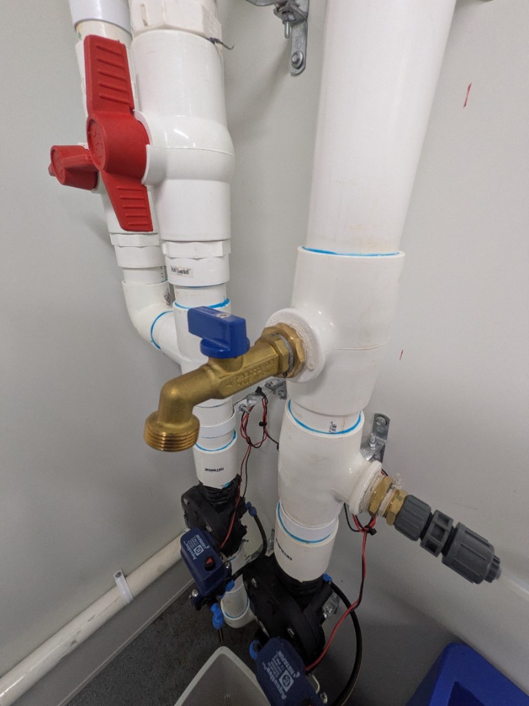
| Item | Detail |
|---|---|
| Type | Brass quarter-turn tap with blue handle, on a PVC T in the wall manifold |
| Purpose | Draw treated-effluent / recycled-water samples inside the control room |
| Isolation | Red-handled ball valves on the parallel vertical PVC lines beside the tap |
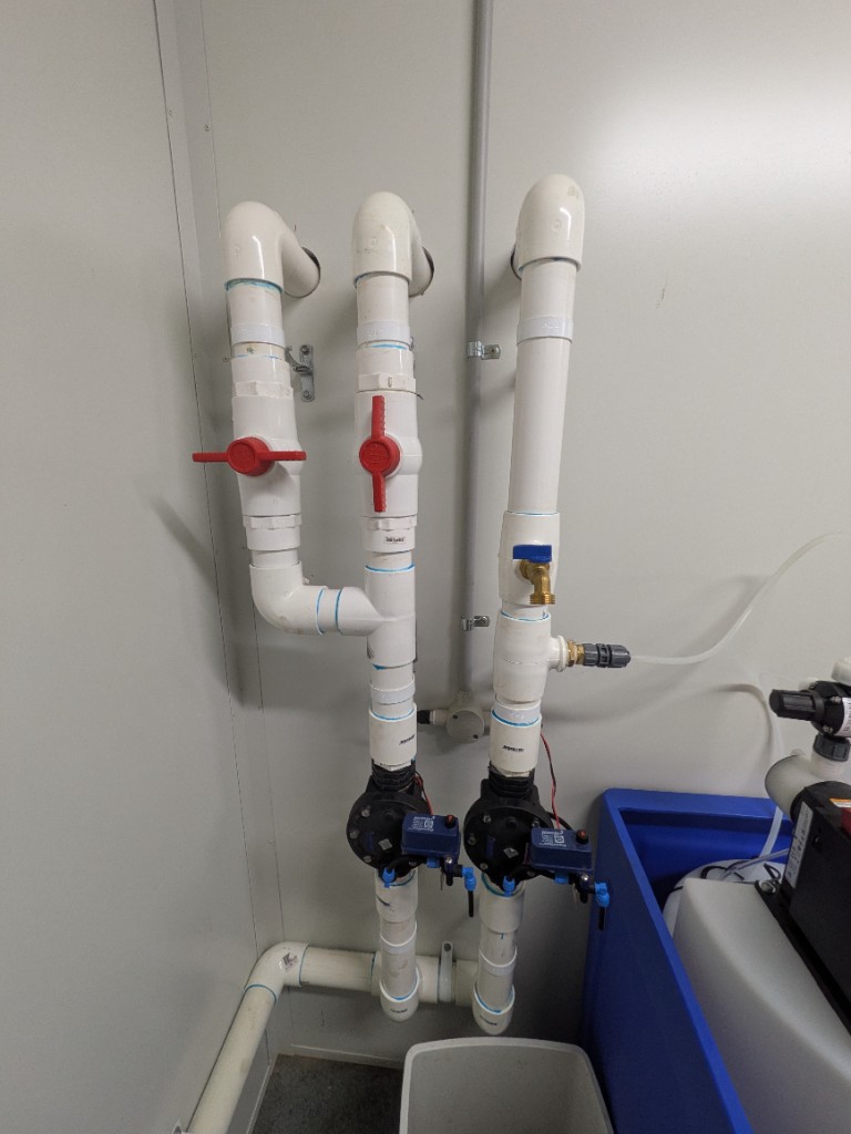
Distribution Manifold
Wall-mounted PVC manifold after disinfection. It splits treated effluent to the land application areas (absorption / irrigation) and to the recycled water storage tanks.
| Item | Detail |
|---|---|
| Manual Valves | Red-handled ball valves — isolate or shut individual absorption (LAA) legs |
| Automatic Solenoids | Netafim Aquative Plus — turn absorption areas on or off, and divert flow to the RWS tanks |
| Daily Limit Logic | When the programmed daily discharge volume is reached, the N/O irrigation solenoid closes and the N/C solenoid opens to the RWS tanks (resets at midnight) — see 3.2.14 Recycled Water Storage |
Field layout of the irrigation zones: 3.2.8 Effluent Disposal.
Flow Meter
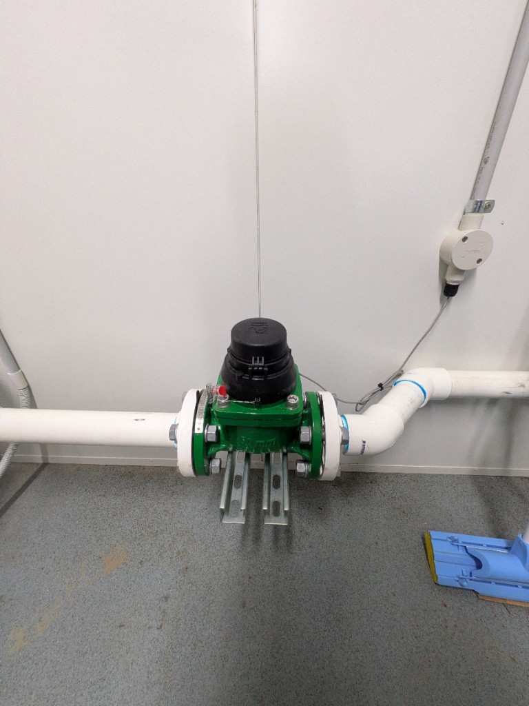
| Item | Detail |
|---|---|
| Type | Mechanical, 50 mm, flanged in the treated-effluent PVC line |
| Pulse Output | One pulse per 1,000 L |
| Mounting | Horizontal, Unistrut-supported on the control-room wall |
The pulse output is the volume signal used for discharge-limit and irrigation logic (see 3.2.12 AdvanTex Secondary daily discharge limit).
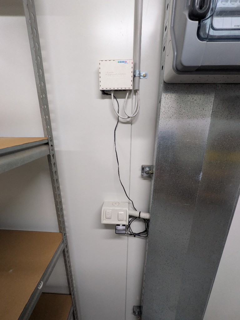
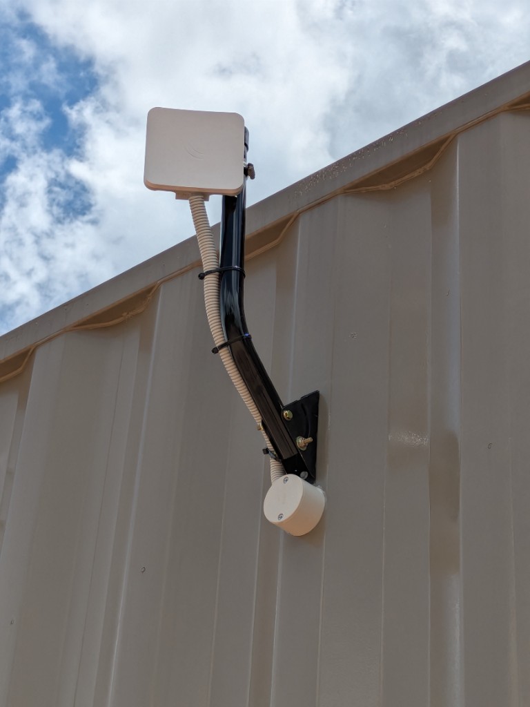
Communications
| Item | Detail |
|---|---|
| Router | MikroTik RouterBOARD, wall-mounted in the control room |
| Outdoor transmitter | MikroTik panel, J-mast mounted on the control-room container wall |
| T-COM | Network path for Orenco T-COM telemetry (remote monitoring and alarms) — see 3.2.15 O&M and Contingency |
| Contractor access | WiFi for contractors working in the control room |
Power Distribution Board
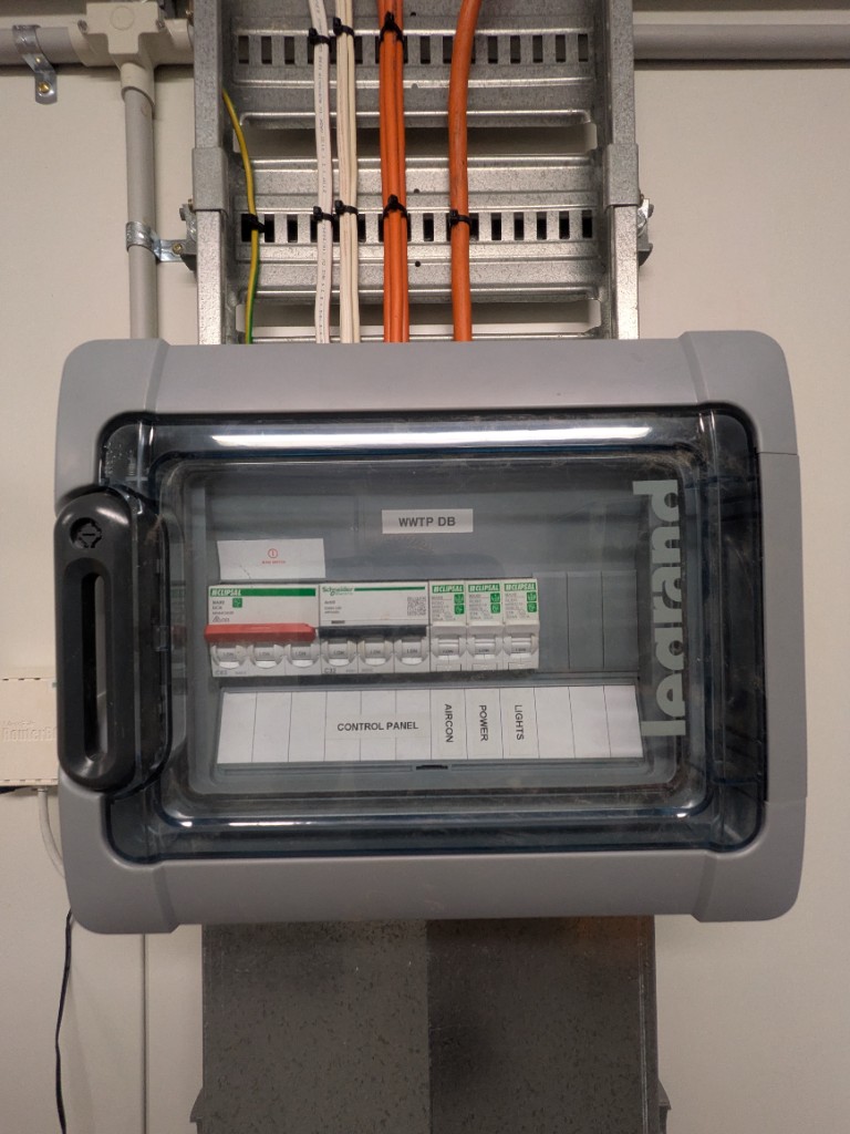
Wall-mounted Legrand enclosure labelled WWTP DB. Estate grid connection and other boards: 3.3.1 Grid.
| Circuit | Breaker |
|---|---|
| Main | Clipsal 63 A isolator (red toggle) |
| Control Panel | Schneider Electric Acti9 iC60N C32 |
| Aircon | Clipsal MAX4 16 A |
| Power | Clipsal MAX4 16 A |
| Lights | Clipsal MAX4 10 A |
Electrical Pit
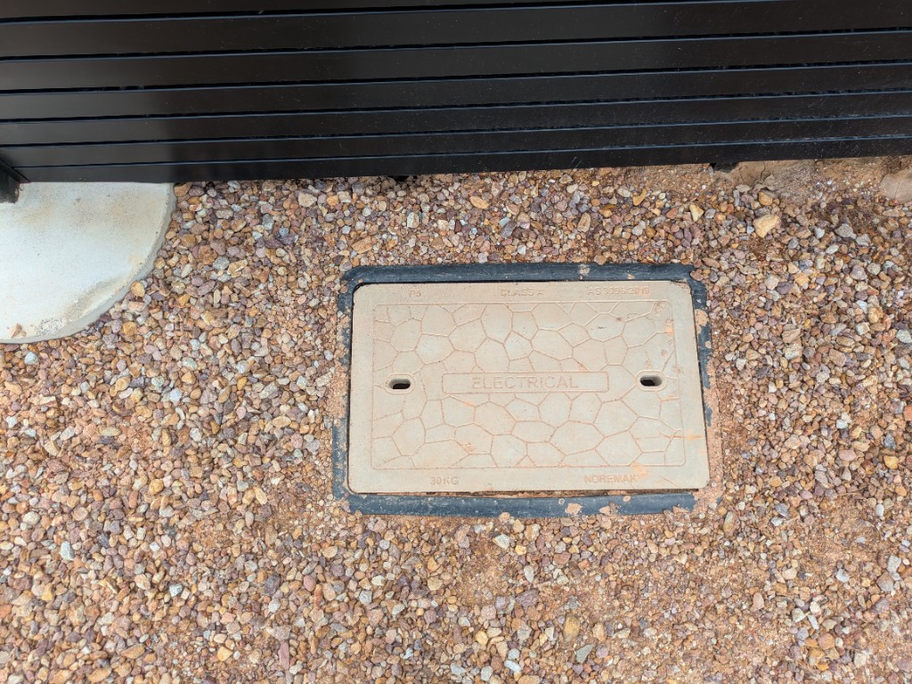
In-ground electrical pit immediately behind the control-room container. The lid is labelled ELECTRICAL.
| Item | Detail |
|---|---|
| Cover | Noremak, Class A, AS 3996:2019, 30 kg |
| Lid marking P5 | Cover model marking — not the estate Pit 5 Distribution Box |
Air Conditioning
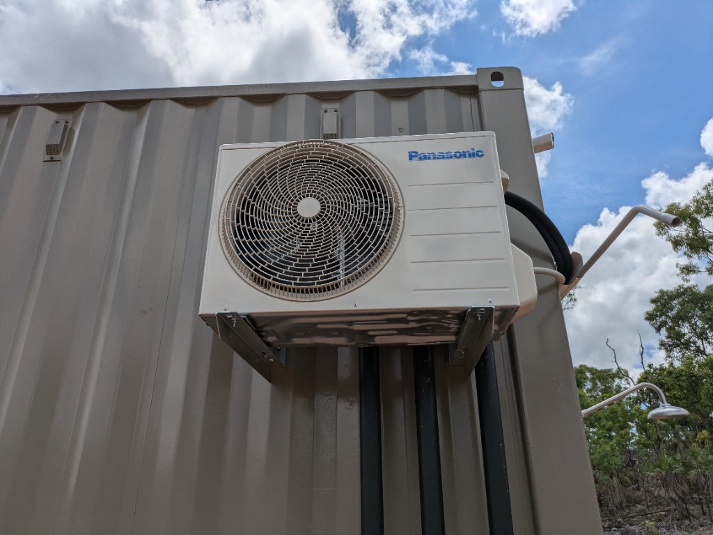
The control room is climate-controlled by a Panasonic split system, fed from the Aircon 16 A circuit on the WWTP DB.
| Item | Detail |
|---|---|
| Indoor | Wall-mounted Panasonic inverter inside the control room |
| Outdoor | Panasonic condenser, bracket-mounted on the container wall |
Floodlight and Security Camera
Mounted on an exterior corner of the control-room container.
| Item | Detail |
|---|---|
| Camera | White bullet camera at the top of the corner, aimed down and out |
| Floodlight | LED floodlight on a bracket below the camera |
| Cabling | Flexible conduit from a wall junction box to the floodlight |
Version Control
| Version | Date | Description |
|---|---|---|
| 2.0 | 2026-06-22 | Rewritten for AdvanTex WWTP per O&M Manual V1.1 |
| 2.1 | 2026-08-30 | Photo of Grundfos chlorine dosing pump and tank in the WWTP control room |
| 2.2 | 2026-08-30 | Photo of chlorine injection point in the WWTP control room |
| 2.3 | 2026-08-30 | Photo of sampling tap in the WWTP control room |
| 2.4 | 2026-08-30 | Photos of microfilter, distribution manifold, and 50 mm flow meter (1 pulse per 1,000 L) |
| 2.5 | 2026-08-30 | Photo of twin Sanitron UV units in the WWTP control room |
| 2.6 | 2026-08-30 | Photo of MikroTik WiFi router for T-COM and contractor internet |
| 2.7 | 2026-08-30 | Photo of WWTP DB circuit breakers in the control room |
| 2.8 | 2026-08-30 | Photo of Panasonic indoor air-conditioning unit |
| 2.9 | 2026-08-30 | Photo of Panasonic outdoor air-conditioning unit on the container |
| 2.10 | 2026-08-30 | Photo of electrical pit behind the control room |
| 2.11 | 2026-08-30 | Photo of MikroTik WiFi transmitter on the control-room mast |
| 2.12 | 2026-08-30 | Photo of floodlight and security camera on the control room |
| 2.13 | 2026-08-30 | Photo of purple and green potable-water valve boxes beside the control room |
Next Review Date: 2026-12-22