3.2.19 T-COM Local HMI
The local HMI is the colour LCD touchscreen (HMI1) on the Orenco T-COM control panel in the WWTP control room. It is the onsite graphical face of the same controller that serves the web interface and T-COM Viewer.
Shared plant context, backplate tags, and Pt# baselines: 3.2.16 T-COM Control Interface. Control room location: 3.2.13 Control Room.
Authorised Personnel Only
Only trained personnel should operate the HMI. Default practice: view status and report to ENVR — do not change setpoints without authority.
Where It Is
| Item | Detail |
|---|---|
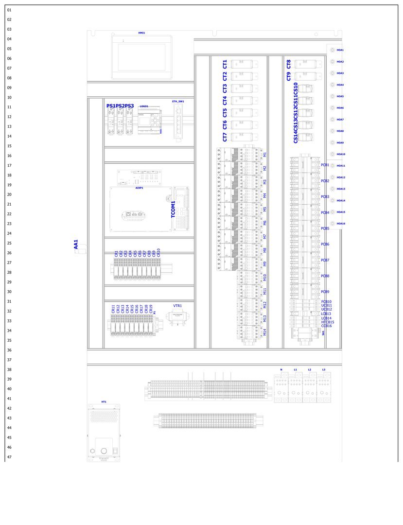
| Tag | HMI1 on the panel door (LCD) / backplate |
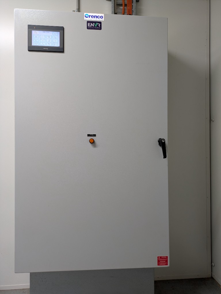
| Panel | Orenco TCOM enclosure (ENVR Solutions) in the 20 ft control-room container |
| Power | Panel powered from WWTP DB CONTROL PANEL breaker |
| Network | Linked via ETH_SW1 to TCOM1 (same plant network as the web server) |
Use case. Confirm you are at the right enclosure in the control room before touching anything — Orenco / ENVR door, LCD top-left, AOH column beside the screen.
How to get there. Walk into the WWTP control-room container; the T-COM panel is wall-mounted. Wake the LCD by touching it if the backlight is off.
Use case. Match backplate tags (HMI1, TCOM1, HOA column) when an electrician or ENVR is talking you through a circuit.
How to get there. Open the panel door (authorised / trained only) — layout drawing of the backplate.
When You Would Use the Local HMI
Use case. You are already in the control room — after a walkover, a smell complaint, or because an alarm page told you to look. The HMI is the fastest way to see pump run state and active faults without unlocking a laptop. For offsite checks use the web; for monthly log files use Viewer.
| Situation | What you do at the HMI |
|---|---|
| Arrived after an alarm page | Wake the screen → note any alarm banner → open the tank/process status for the group that paged → photograph → call ENVR |
| End of walkover | Glance PA1 / RT1 / DT1 status and UV/fan — confirm nothing stuck running or stuck Off |
| Electrician finished AOH work | Confirm each circuit is back in AUTO, then check HMI still shows normal Auto call |
| Clock or network looks wrong | Confirm panel power and ETH path; fix clock via web/Viewer if directed — HMI alone may not be the clock editor |
| Need deep timer edit | Stop — that is ENVR on Viewer / web with authority, not a casual HMI tweak |
Auto-Off-Man (AOH / HOA) Switches
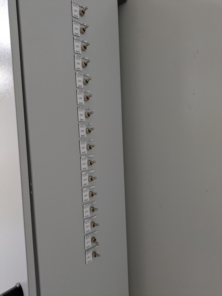
Beside the LCD, the panel door has a vertical column of 16 three-position toggles (Orenco drawings call them HOA; the engraved legend reads AUTO / OFF / MAN). These are physical overrides for each motor / output circuit — independent of which software UI you use.
Use case. Software can call a pump all day; if the switch is in OFF, nothing turns. Conversely, MAN forces that output on even when T-COM would leave it idle — useful for a directed test, dangerous if forgotten. After any maintenance visit, walk the column before you leave: everything that should be automatic must read AUTO.
How to get there. On the panel door, immediately right of the LCD — sixteen toggles top → bottom (list below). No software path; physical only.
| Position (panel legend) | Effect |
|---|---|
| AUTO | Normal — T-COM / floats / timers control the output |
| OFF | Forces that output off regardless of T-COM call |
| MAN | Forces that output on (manual / Hand — bypasses normal sequencing; only when directed) |
Circuit List (Top → Bottom)
| # | Label on door |
|---|---|
| 1 | PRE-ANOXIC PUMP 1 |
| 2 | PRE-ANOXIC PUMP 2 |
| 3 | RECIRC PUMP 1 |
| 4 | RECIRC PUMP 2 |
| 5 | RECIRC PUMP 3 |
| 6 | RECIRC PUMP 4 |
| 7 | PRE-ANOXIC RETURN |
| 8 | DISCHARGE PUMP 1 |
| 9 | DISCHARGE PUMP 2 |
| 10 | AIR FAN 1 |
| 11 | UV UNIT 1 |
| 12 | UV UNIT 2 |
| 13 | LCH-PER PUMP 1 |
| 14 | STRIPPER 1 |
| 15 | IRRIGATION FIELD 1 |
| 16 | IRRIGATION FIELD 2 |
Door Label vs Plant Function
Switch 16 is engraved IRRIGATION FIELD 2, but on this site it controls feed to the recycled water storage (RWS) tanks, not a second irrigation field. Field irrigation / LAA is IRRIGATION FIELD 1. See 3.2.14 Recycled Water Storage and 3.2.8 Effluent Disposal.
Leave circuits in AUTO unless ENVR or an electrician directs MAN or OFF for maintenance.
What the Touchscreen Shows
The Maple Systems LCD (HMI1) is the graphical face of the same Orenco T-COM controller as the web and Viewer. Screen photos below are cropped and flattened from onsite captures (2026-10-19).
On every page: Main Menu returns to the hub; Previous steps back one screen in that group. Do not change pink/blue setpoints without ENVR authority.
Intro Screen
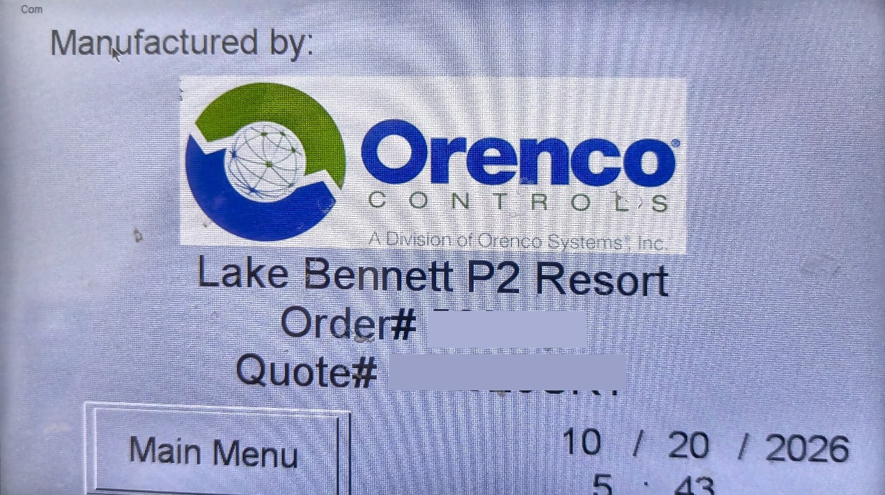
Use case. Confirm this panel is Lake Bennett P2 Resort before you call Orenco / ENVR — wrong site identity means you are on the wrong controller. Order and quote numbers on the glass are redacted in this public manual.
How to get there. Default after power-up / wake, or Main Menu → Intro Screen. Tap Main Menu (bottom left) to leave.
Main Menu
Use case. Navigation hub for every walkover — pick the tank or subsystem that matches the alarm or smell complaint, then drill in.
How to get there. From Intro Screen tap Main Menu, or tap Main Menu on any other HMI page.
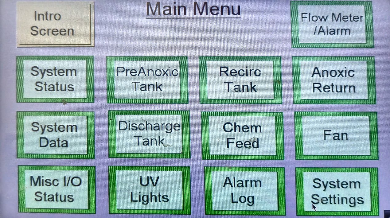
| Main Menu button | Opens |
|---|---|
| Intro Screen | Site / manufacturer ID |
| Flow Meter / Alarm | FM1 daily flow log |
| System Status | One-page OK / fault summary |
| PreAnoxic Tank | PA1 status (+ timers / flow / amps) |
| Recirc Tank | RT1 status (+ manual timers / pump flow) |
| Anoxic Return | PRA status (+ pump settings) |
| System Data | System data (if used on this build) |
| Discharge Tank | DT1 status (+ timers / flow / amps) |
| Chem Feed | Liquid chem (alkalinity) status / settings |
| Fan | AX fan (XF1) status / setting |
| Misc I/O Status | Contactor / alarm I/O snapshot |
| UV Lights | UV1 / UV2 status / setting |
| Alarm Log | Event history |
| System Settings | Year, alarm delays, IP — ENVR only |
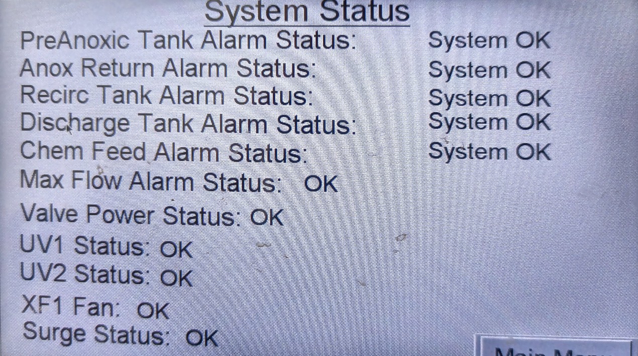
System Status
Use case. First glance after an alarm page or at the end of a walkover — which subsystem is not OK (PA / return / recirc / discharge / chem / max flow / UV / fan / surge) before you open a detail page.
How to get there. Main Menu → System Status.
Pre-Anoxic Tank (PA1)
Primary transfer pumps toward secondary treatment. Process context: 3.2.11.
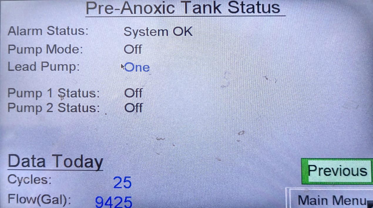
Pre-Anoxic Tank Status
Use case. High-level alarm, “transfer pumps not alternating,” or a quick health check — alarm state, lead pump, Pump 1/2 On/Off, today’s cycles and gallons.
How to get there. Main Menu → PreAnoxic Tank.
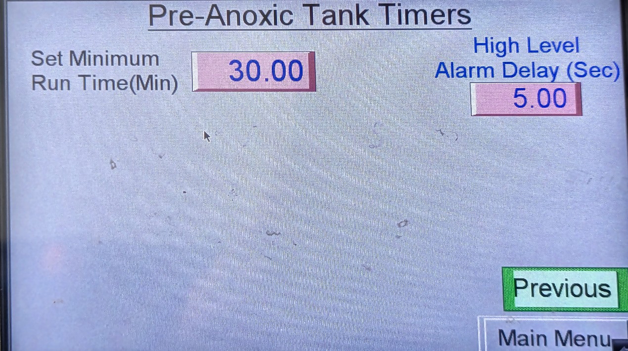
Pre-Anoxic Tank Timers
Use case. Read (or ENVR-edit) minimum run time and high-level alarm delay when short-cycling or nuisance high-level trips are suspected. Baseline context: 3.2.16 Page e.
How to get there. Main Menu → PreAnoxic Tank → open the Timers page from that status group. Previous returns toward Status.
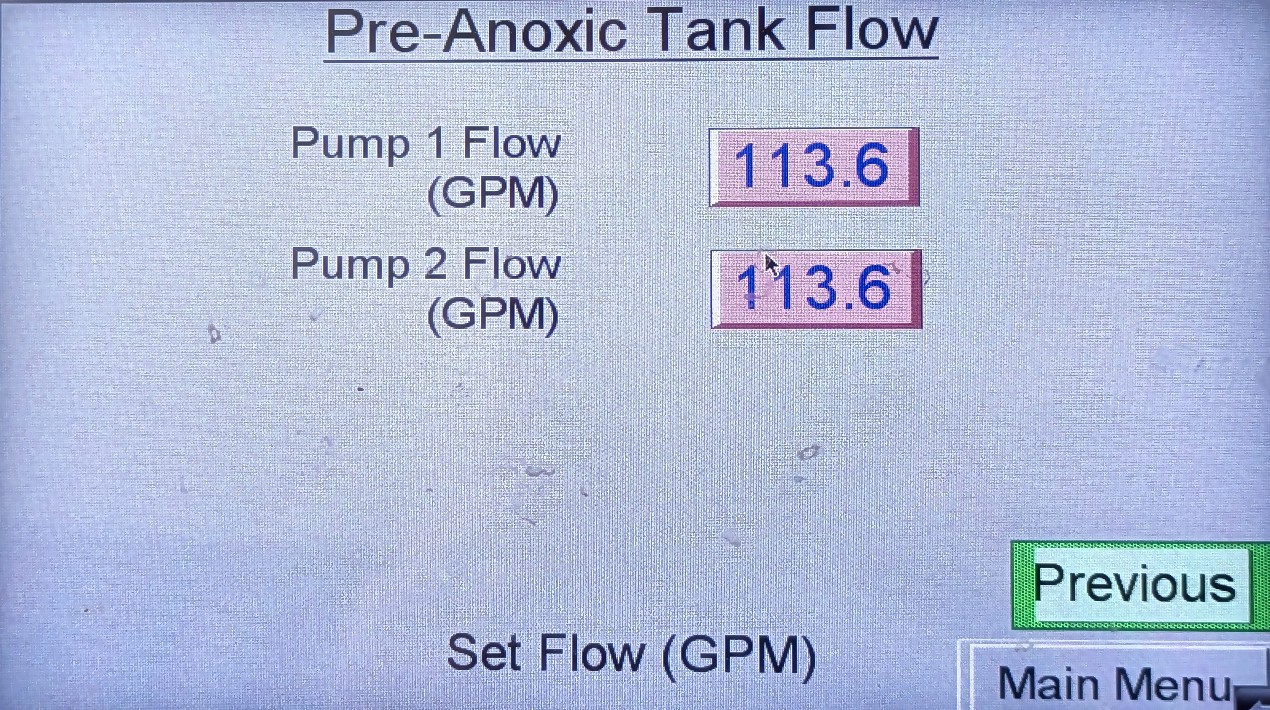
Pre-Anoxic Tank Flow
Use case. Check / confirm per-pump flow (GPM) after a pump swap or when daily gallons look wrong against amps.
How to get there. Main Menu → PreAnoxic Tank → open the Flow page from that status group.
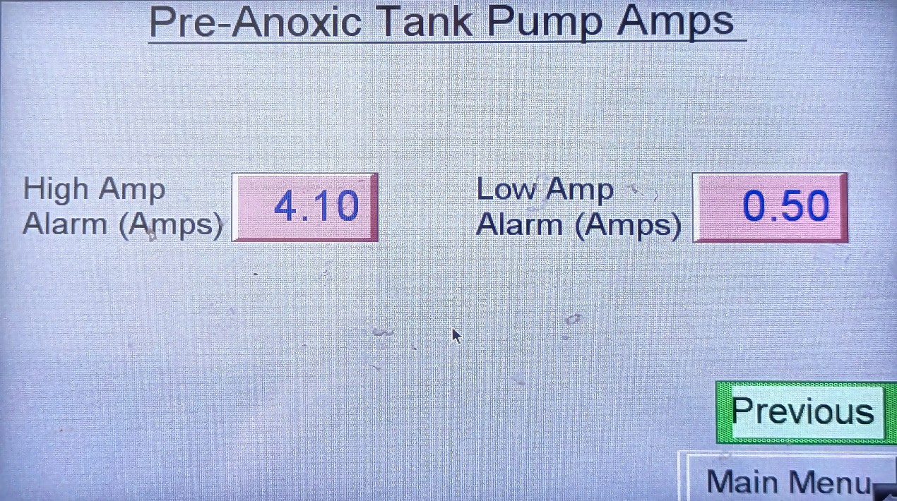
Pre-Anoxic Tank Pump Amps
Use case. Bound a seized, dry, or overloaded PA pump — compare live amps to the high/low alarm windows before calling ENVR with numbers.
How to get there. Main Menu → PreAnoxic Tank → open the Pump Amps page from that status group.
Recirc Tank (RT1)
AdvanTex recirculation. Process context: 3.2.12.
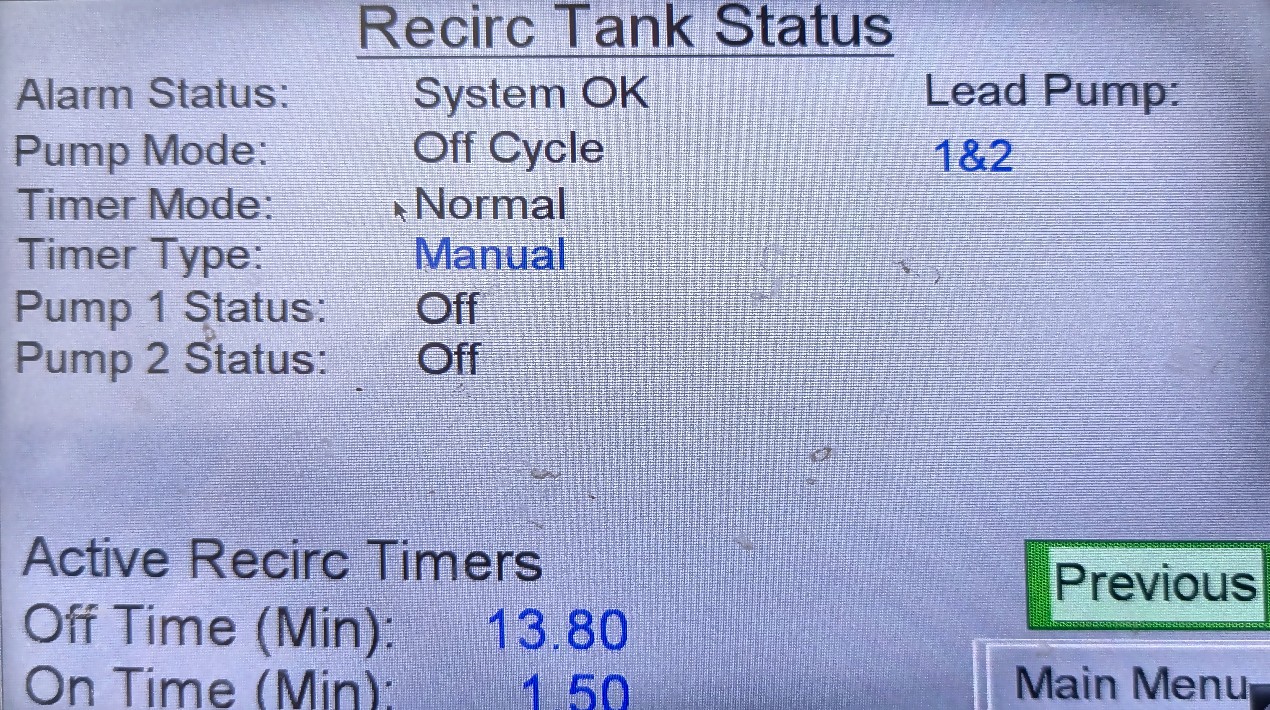
Recirc Tank Status
Use case. “Is recirc alive?” after an overnight alarm, smell complaint, or weekly check — alarm, pump mode, timer mode/type, lead pumps, active on/off times. If Timer Type shows Manual and nobody authorised it, report it.
How to get there. Main Menu → Recirc Tank.
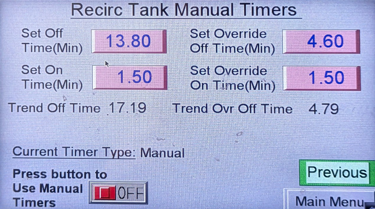
Recirc Tank Manual Timers
Use case. Confirm manual on/off and override times when Status shows Manual, or when ENVR is running a controlled trial. Leaving Use Manual Timers On overrides auto/trend maths — estate staff: read only unless directed.
How to get there. Main Menu → Recirc Tank → open Manual Timers from that status group.
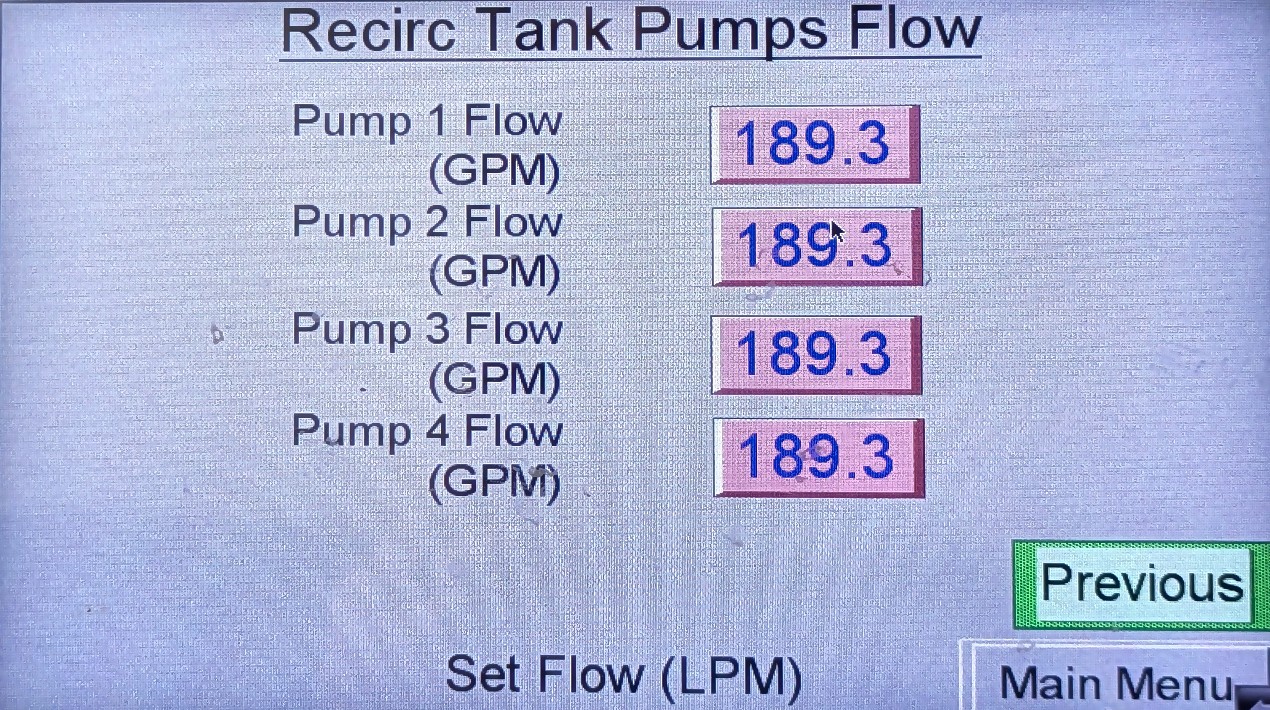
Recirc Tank Pumps Flow
Use case. See whether each recirc pump is contributing volume after a high-flow day or when one pump looks dead on Status.
How to get there. Main Menu → Recirc Tank → open the Pumps Flow page from that status group.
Anoxic Return (PRA)
Filtrate return / nitrogen loop. Process context: 3.2.12.
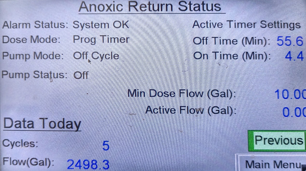
Anoxic Return Status
Use case. Return flow seems absent, nitrogen performance under review, or after work on the return pump — confirm enable/run state before leaving the container.
How to get there. Main Menu → Anoxic Return.
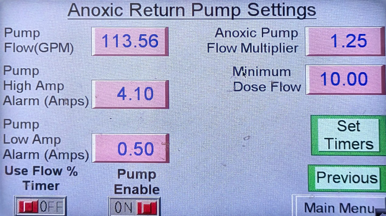
Anoxic Return Pump Settings
Use case. Confirm Pump Enable is still On after maintenance; read flow, multiplier, amp windows. Set Timers opens the return timer page. Baselines: 3.2.16 Page o.
How to get there. Main Menu → Anoxic Return → open Pump Settings from Status; use Set Timers from this page if you need the timer sub-page.
Discharge Tank (DT1)
Dose / discharge toward LAA and RWS. Process context: 3.2.8, 3.2.14.
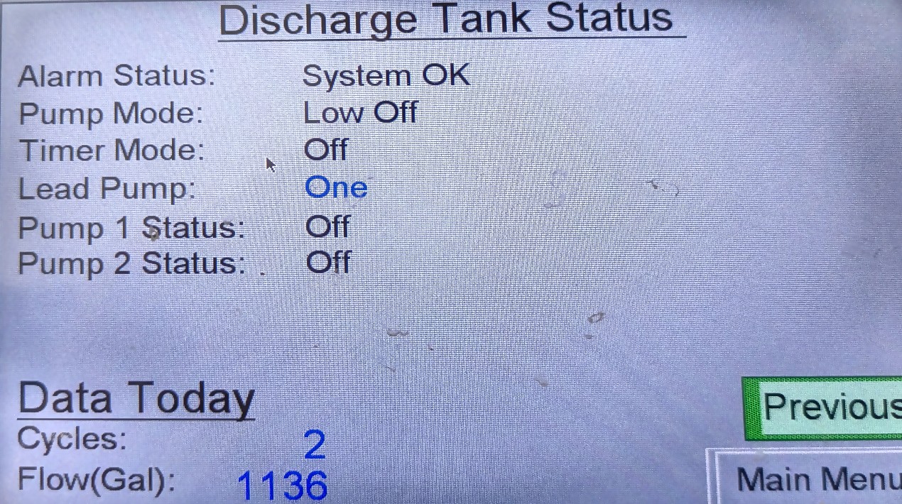
Discharge Tank Status
Use case. Irrigation “not happening,” DT1 high-level page, or end-of-walkover check — which discharge pump is called, alarm state, run status. Also confirm door AOH switches 8–9 and 15–16 are not left OFF.
How to get there. Main Menu → Discharge Tank.
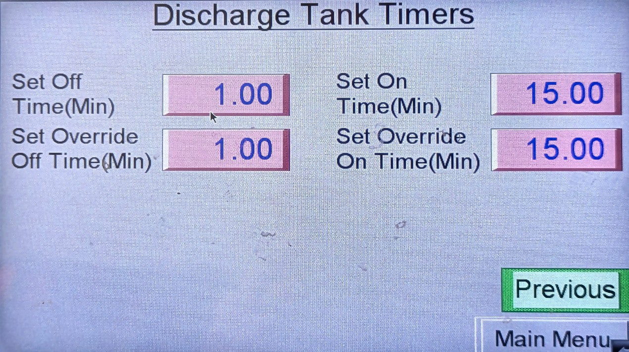
Discharge Tank Timers
Use case. Read discharge on/off (and override) times when irrigation dose windows look wrong. ENVR edits only. Baselines: 3.2.16 Page r.
How to get there. Main Menu → Discharge Tank → open Timers from that status group.
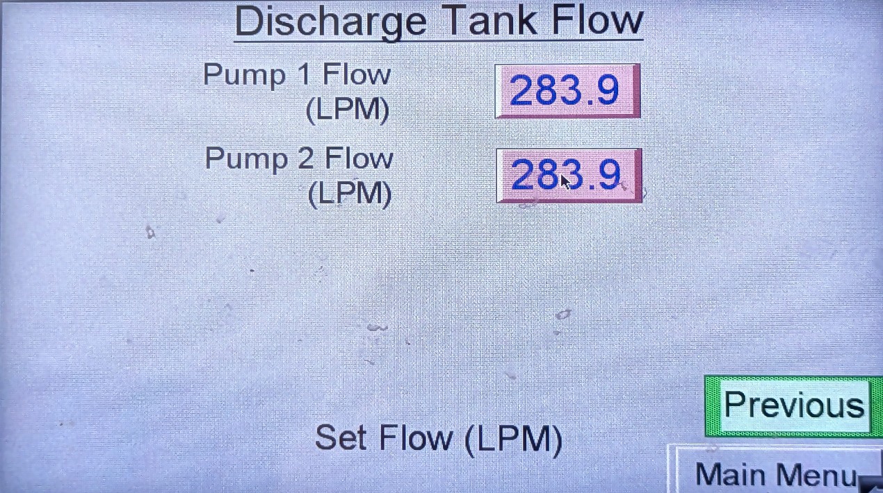
Discharge Tank Flow
Use case. How much left the dose tank toward LAA / RWS — compare after wet weather, a high-level trip, or against FM1 daily totals.
How to get there. Main Menu → Discharge Tank → open Flow from that status group.
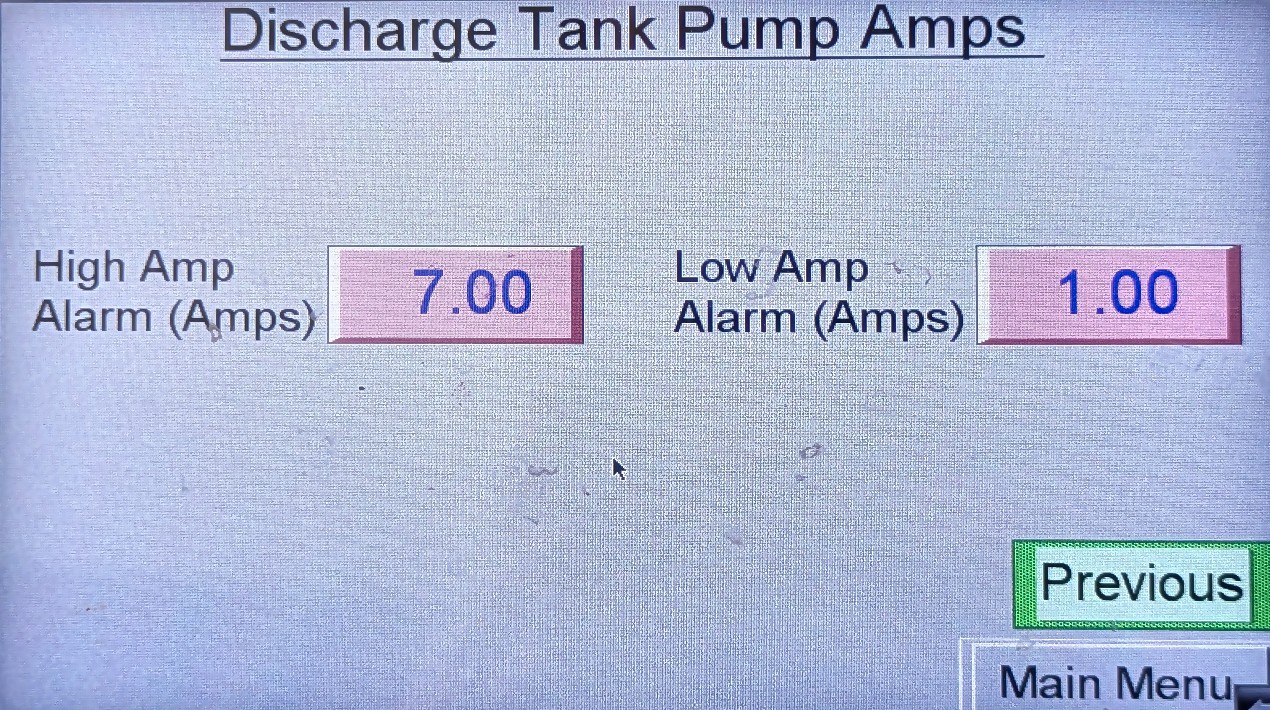
Discharge Tank Pump Amps
Use case. Bound a discharge pump fault (high/low amps) before a service call — photograph and report numbers to ENVR.
How to get there. Main Menu → Discharge Tank → open Pump Amps from that status group.
Chem Feed, Fan, UV, Misc I/O
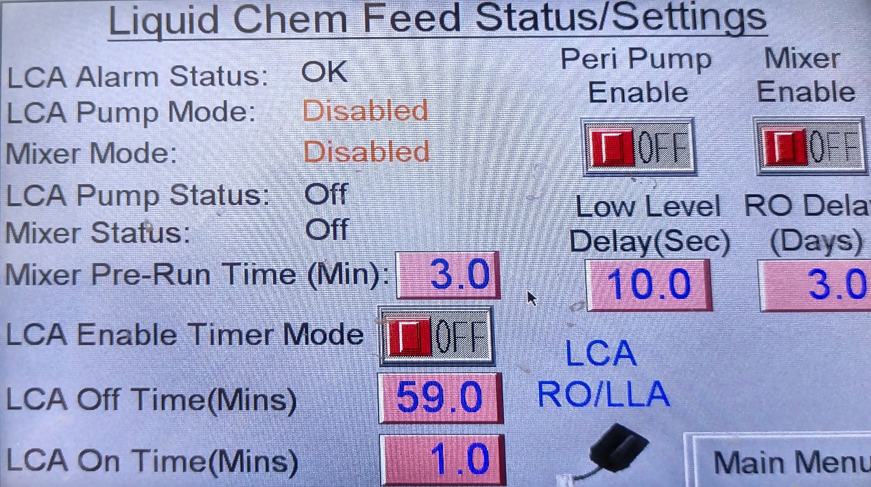
Liquid Chem Feed Status/Settings
Use case. After a tote change, when lab alkalinity slips, or when chem looks silent — confirm peri / mixer enables and status. Leaving enables OFF after maintenance is a common miss. Baselines: 3.2.16 Page v.
How to get there. Main Menu → Chem Feed.
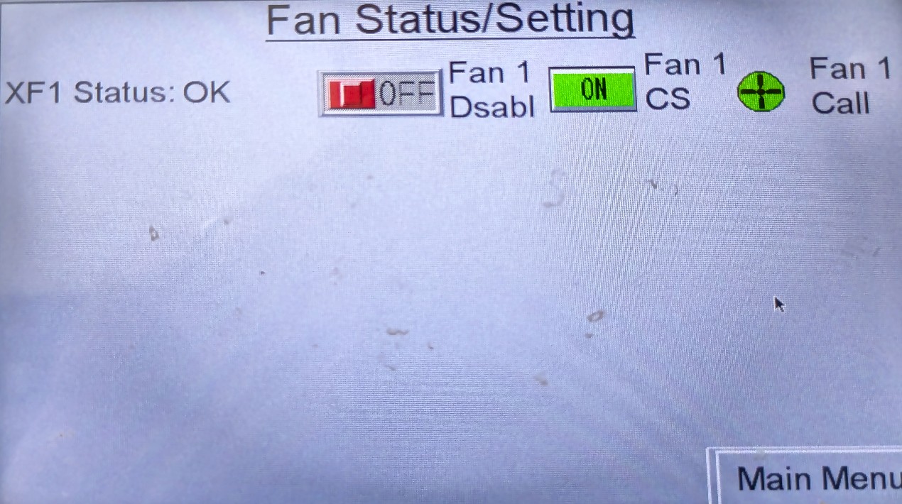
Fan Status/Setting
Use case. Odour increase, fan current fault, or “fan not running” report — confirm XF1 is not disabled and note any fault. Context: 3.2.12.
How to get there. Main Menu → Fan.
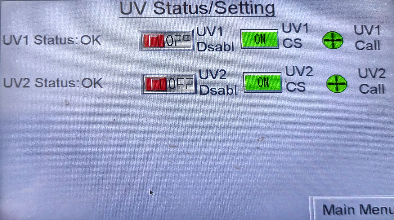
UV Status/Setting
Use case. UV fault page, lamp work, or recycled-water quality concern — check UV1 / UV2. A UV fault does not stop the pumps on this design. Context: 3.2.13.
How to get there. Main Menu → UV Lights.
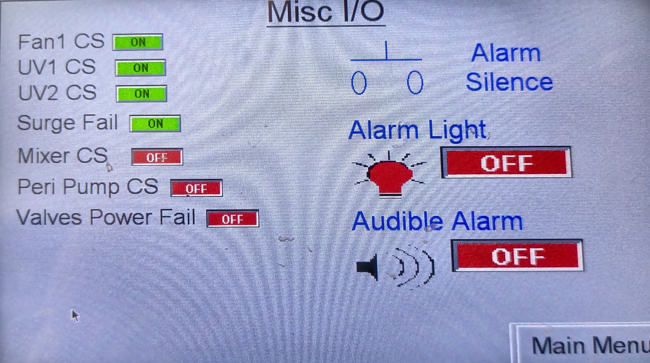
Misc I/O
Use case. Contactor / digital I/O snapshot when Status says a motor is called but nothing is running — pair with the matching AOH switch on the door.
How to get there. Main Menu → Misc I/O Status.
Flow Log and Event History
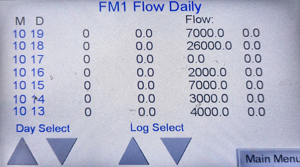
FM1 Flow Daily
Use case. Daily discharge / plant flow totals for a busy weekend, high-flow alarm investigation, or before a compliance download. Pair with 3.4 Flow Monitoring where useful.
How to get there. Main Menu → Flow Meter / Alarm.
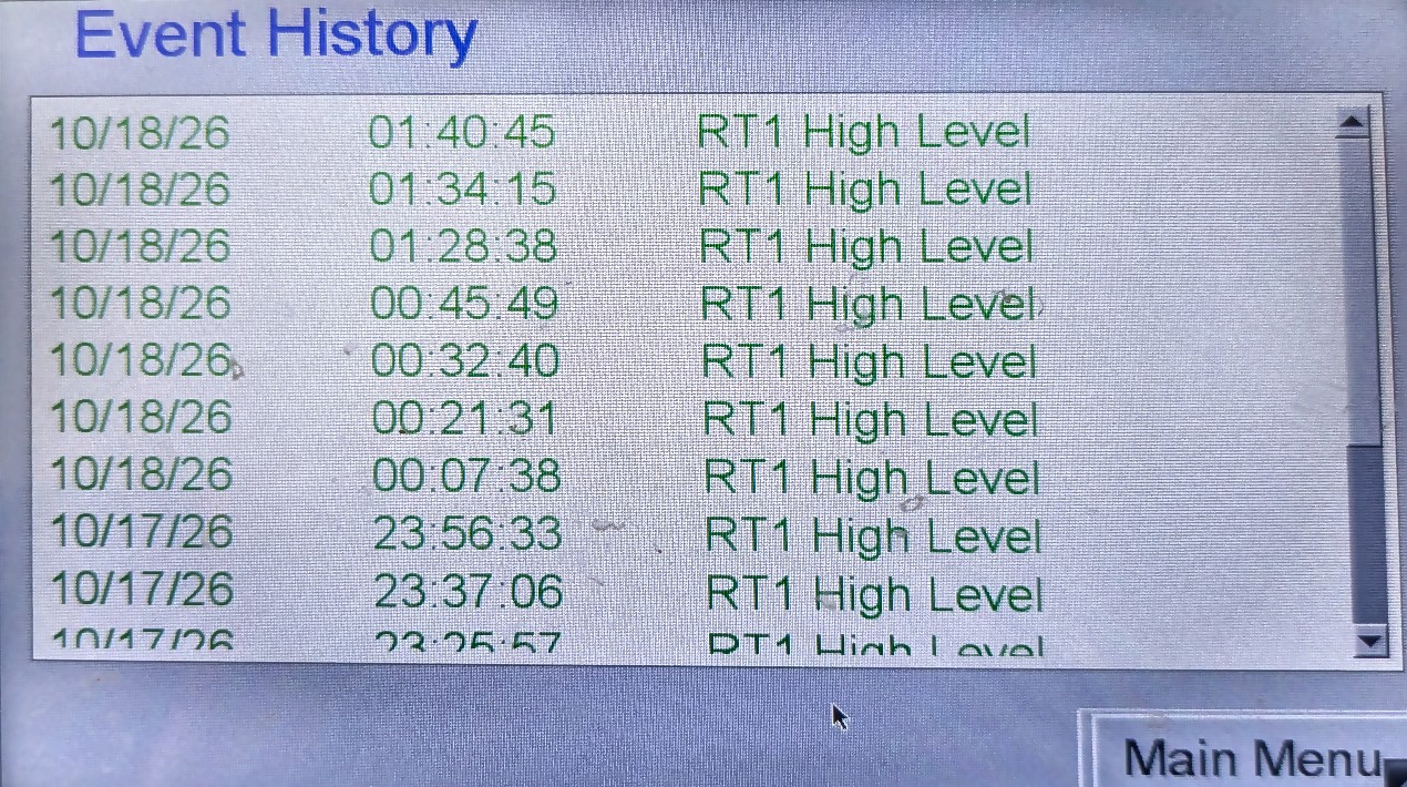
Event History (Alarm Log)
Use case. After a page or when someone asks “has this happened before?” — scroll date/time/event (example capture: repeated RT1 High Level). Photograph the relevant lines for ENVR.
How to get there. Main Menu → Alarm Log.
System Settings (Authorised / ENVR)
Do not change setpoints or network settings without authority.
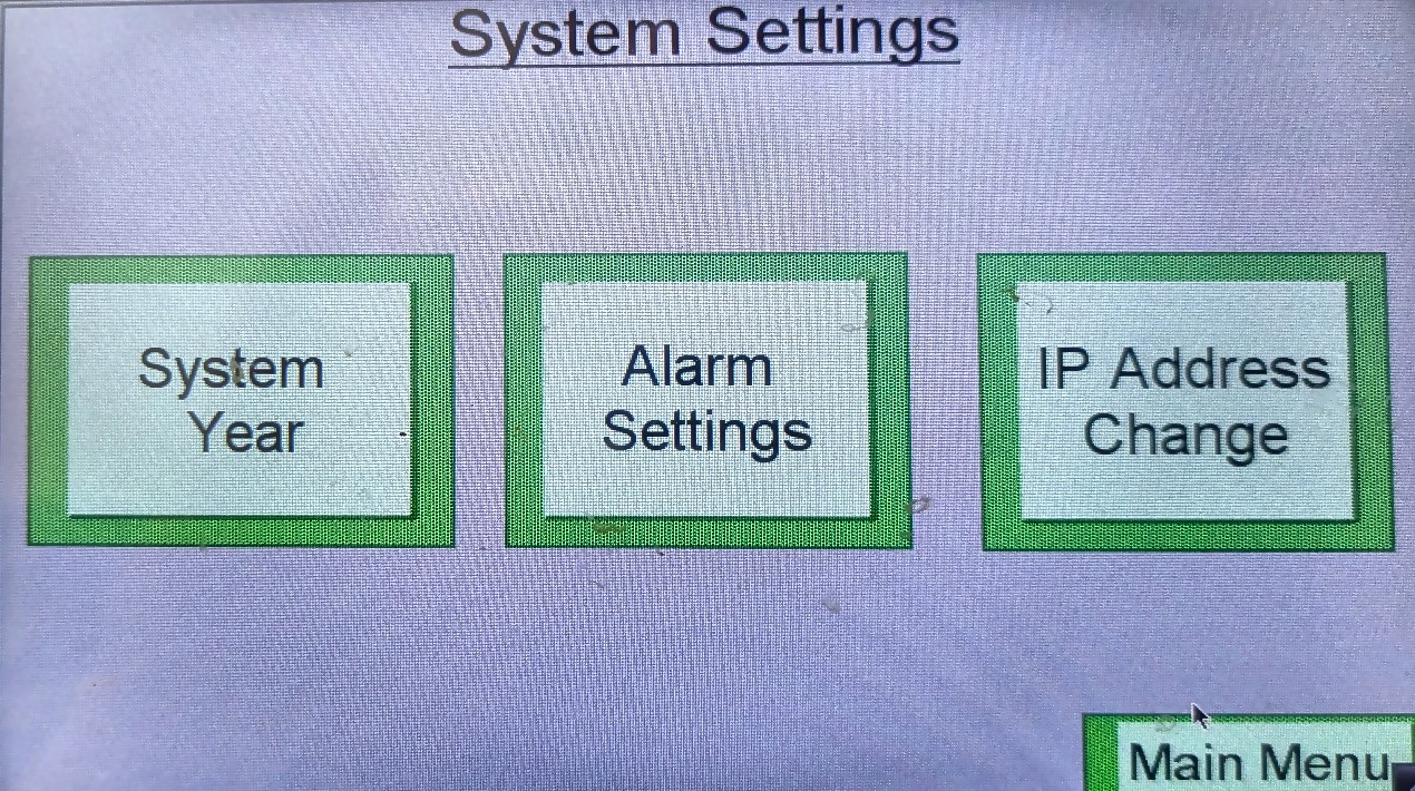
System Settings
Use case. Hub for clock year, alarm delays, and IP change — only when ENVR directs a change.
How to get there. Main Menu → System Settings.
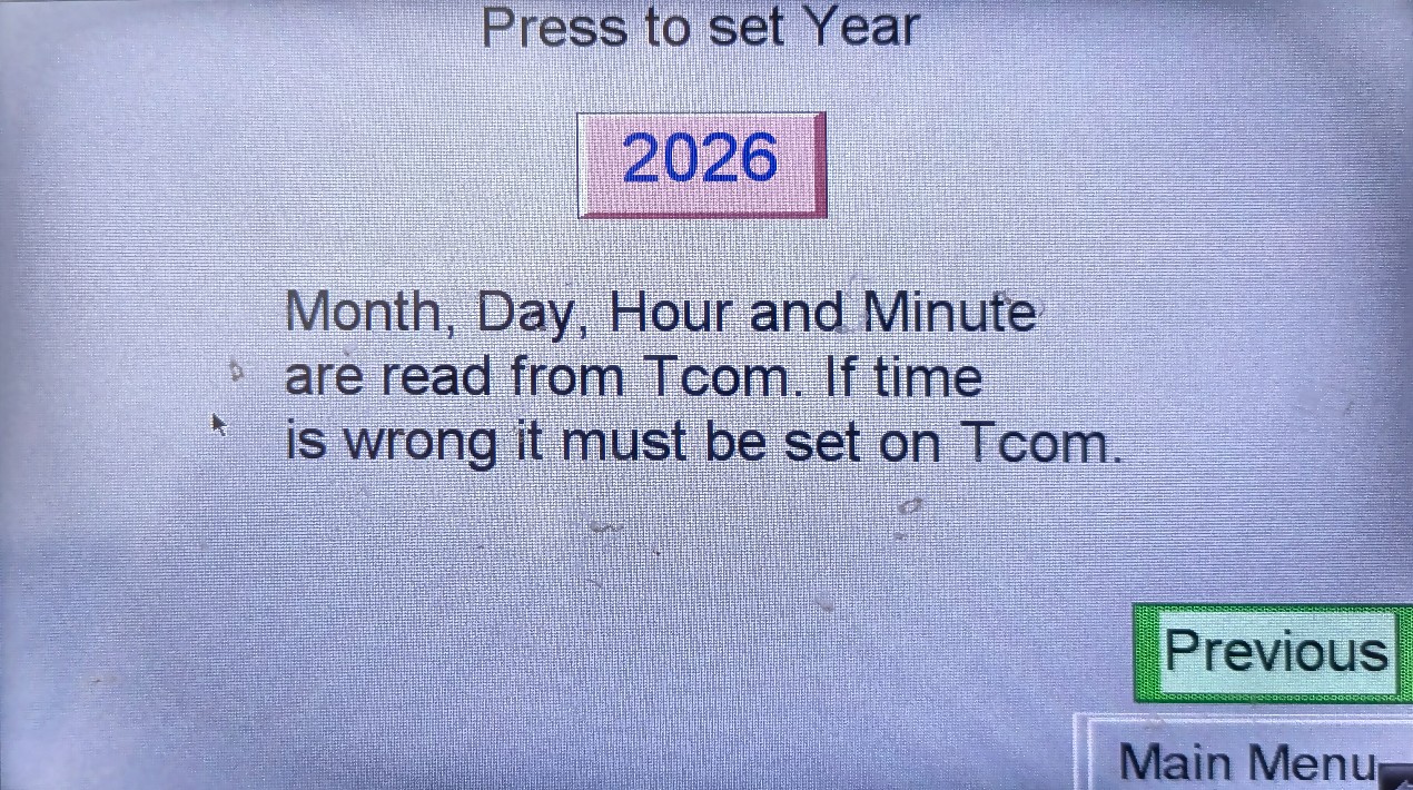
System Year
Use case. Year on the HMI looks wrong after a long outage. Month/day/time are read from T-COM — if those are wrong, set them on T-COM (web/Viewer), not here.
How to get there. Main Menu → System Settings → System Year.
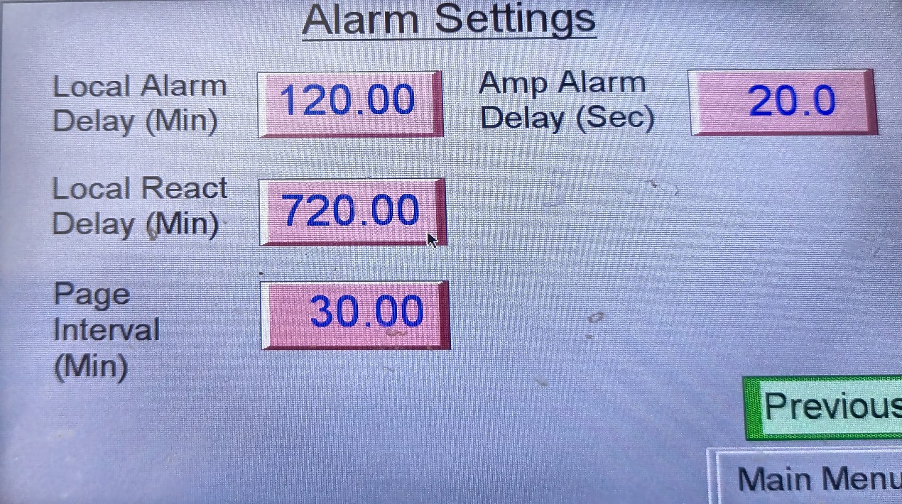
Alarm Settings
Use case. Explains a quiet plant: local horn delay (baseline 120 min), reactivate delay, page interval (30 min), amp-alarm debounce. Change only with ENVR. Baselines: 3.2.16 Pages A/B/F/H.
How to get there. Main Menu → System Settings → Alarm Settings.
Editing from the HMI vs Text Path
Use case. The HMI, web, and Viewer all write the same points. If ENVR constrained a value in Viewer (Sts = C) and left it that way, the touchscreen may refuse edits until someone returns Sts to A. After any authorised Viewer change meant for onsite follow-up, put the point back to Automatic so the next person at the glass is not locked out.
- Same points: The HMI edits the same points as Viewer / web
- Constrained (C): If a point was left constrained from the text/Viewer path, the HMI may not be able to change it until Sts is returned to A (automatic)
- Return to Automatic: After any authorised Viewer edit intended for HMI use, set values back to A
Onsite Checks at the Panel
A short runbook when you walk into the container:
- Confirm WWTP DB CONTROL PANEL breaker is on
- Confirm control-room power, aircon, and WiFi path look normal
- Confirm AOH switches are in AUTO unless work is in progress
- Wake / view the HMI — note any alarm banner or unusual pump cycling
- Photograph / note the symptom and contact ENVR — do not guess setpoints
Full schedule: 3.2.15 O&M and Contingency.
Version Control
| Version | Date | Description |
|---|---|---|
| 1.0 | 2026-10-18 | Split from 3.2.16 — local LCD HMI page |
| 2.0 | 2026-10-18 | Operator use cases for onsite HMI and HOA |
| 2.1 | 2026-10-20 | Photo of panel door with Main Menu; menu buttons documented from site |
| 2.2 | 2026-10-20 | Photo of AOH switches; circuit list and AUTO/OFF/MAN legend from site |
| 2.3 | 2026-10-20 | Noted IRRIGATION FIELD 2 AOH is RWS storage tanks, not a second LAA field |
| 2.4 | 2026-10-20 | Added cropped/flattened Maple Systems HMI screen gallery from site photos |
| 2.5 | 2026-10-20 | Use case and navigation path caption under every HMI / panel image |
| 2.6 | 2026-10-20 | Redacted Order# / Quote# on Intro Screen (text and image) |
| 2.7 | 2026-10-20 | Style guide compliance — H1 matches nav; Title Case headings |
Next Review Date: 2027-04-20